100W MONOBLOC 2004.
Slightly edited March 2014.
Re-edited 2017, with much better schematic quality and a few
slight improvements.
Content of this page......
Fig 1. Picture of two 100W UL-AB1 mono amps from 2004.
General description.
Fig 2. SHEET 1 power amp schematic, re-drawn 2017.
Fig 3. SHEET 2 power supply schematic, re-drawn 2017.
Fig 4. SHEET 3 bias pots, and protection circuits, re-drawn
2017.
Fig 5. Power vs load graphs.
Fig 6. THD graphs
Full explanations of all included.
I hope everyone enjoys the better quality schematics. I was
over-worked and underpaid during most of my
audio trade career and schematic production for the amps I made
were drawn by hand in about 3 hours.
To draw schematics as I have them now has taken 3 days full
time, with MS Paint.
For those thinking of building a good 100W PP amp, there is this
page plus another one from 2014 at
100W-monobloc3-2014.
Fig 1.
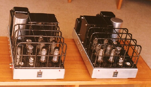
I sold these two amplifiers in early 2004 to a delighted
customer living near Cairns in Queensland
where there is a tropical climate. He wished to power Quad ESL63
speakers used mainly during the
dry season because high humidity can be a problem with ESL. But
the amps would power any other
type of speaker.
Chassis is aluminium, 470 mm long x 260 mm wide x 60mm high with
above chassis content making
total height 220 high, including timber strip feet under each
end of bottom plate to allow air flow through
chassis space and up around each tube through drilled holes
around each power tube. The open
steel grilles over the tubes give just enough protection against
tubes being bent over in sockets and
from falling objects. Weight is approx 22 Kg, ( 49 Lb ), for
each mono amp.
The largest transformer is the output transformer with a 75 mm
stack of 44 mm tongue E&I GOSS E&I
laminations seen behind the output tubes.
The power transformer is 100 mm stack of 38 tongue mm lams, seen
furthest from view. Anyone could
make this amp using the same size PT core used for OPT.
Silicon rectifiers are used, with C-L-C filtering using a choke
of 2H and large value electrolytics to maintain
an impeccably low noise level in B+ rail.
The amp was sold in 2004 with matched 6CA7EH which I feel are
more rugged than EL34,
and excellent sounding.
The 2004 hand drawn schematics for this amp provide ease of
servicing for the amps I sold.
Fig 2. SHEET 1, 100W UL AB1 power amp schematic 2004,
re-drawn 2017.
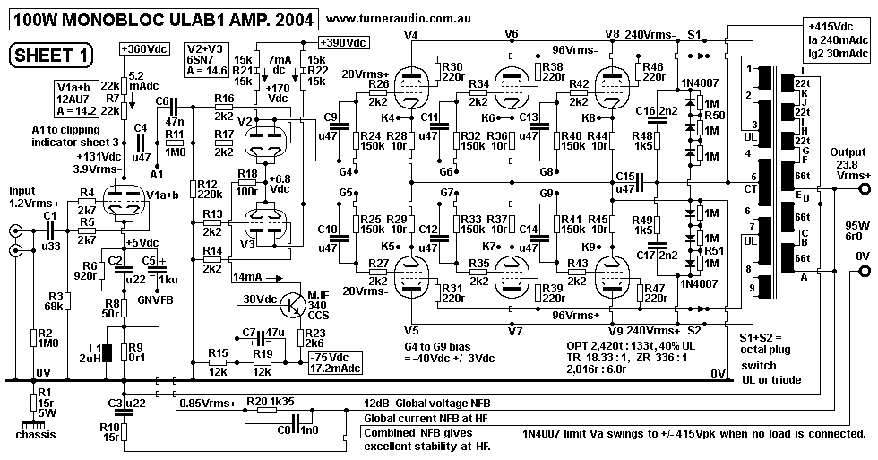
Fig 2 is the 2017 tidied up schematic from 2004 which was
originally hand in previous editions of this page.
Input V1 is paralleled 12AU7 working as a SET differential amp
with source input to grid and GNFB to
its cathodes.
In this amp, I have normal generic 12dB global NFB applied, ie,
series voltage NFB. There is more about
this below. There was no need to use HF gain and phase reduction
with Zobel network across R12.
However, I did use Zobel networks across each half primary of
OPT and across the output terminals to
reduce output tube gain above 50kHz.
There is a LF gain shelving network of C4, C6, R11 and R12,
which prevent any possible LF oscillations
most likely with no load connected.
V2 and V3 are paralleled 6SN7, but could be 6CG7 with no R&C
changes. They work as a long tailed
pair with MJE340 constant current sink for cathodes. Each anode
will easily produce the wanted maximum
of about 30Vrms to drive output EL34. The 15k+15k Anode dc
resistors should be each rated for 3W at least.
The MJE340 has no sonic signature, and does no active
amplification and acts merely as a high impedance
sink of cathode current. It replaces a pentode which may have
been used in 1955 such a 6SH7 with -150Vdc
supply and more complexity. The tube CCS could not perform as
well as the MJE340 as I have it.
The 6SN7 has 30k dc load in parallel with three 150k biasing
resistors of output EL34. This makes
total load = 19.9k, and the maximum possible Va at each anode
> 80Vrms. This is only possible where
no EL34 are plugged in, because whenever 6SN7 Vapk exceeds the
Vdc bias value there is heavy grid
current which limits the Va swing of 6SN7.
Output tubes can be 6 x 6CA7 instead of EL34 pentodes. I sold it
with Russian 6 x 6CA7 which are rugged
beam tetrode close equivalents of EL34 which were first produced
to allow US amp owners to buy US made
tubes for their European amps with European tubes. I found the
Russian 6CA7 look just like Sylvania 6CA7,
and capable of excellent sound, and they were reliable. The 6CA7
seem to have a higher Pda rating and the
anodes become slight cherry red hot at higher idle power than
EL34.
There are TWO global loops of NFB used.
One is normal global series voltage NFB where the network has
1k35 // 1n0 from Vo to 50r at V1 12AU7
cathode. The 1n0 advances the phase of HF signals fed back to
the V1 cathode so that there is good
control of HF amplitude above 10kHz.
The other loop is global series current NFB which I devised to
give better HF stability with capacitance
loads. As F rises, the speaker current passes through 0.1r
shunted by 2uH inductance seen just below V1.
The 0.1r and 2uH have pole at 8 kHz where XL = 0.1r, and have
almost no effect below 8kHz, but
above 8kHz, the output resistance is raised slightly, and the
amp is not forced to maintain low output
resistance above 20kHz where there is no need for low Rout.
This R+L network may not be needed in an amp with a different
OPT to the one I wound.
I found no need for a Zobel R+C network across R12 to shelve the
HF open loop gain to get best possible
HF stability.
Fixed bias is used. There are six adjust pots shown on Sheet 3
below. Volt meter test points are accessible
through 6 access holes in the side of the chassis and near the
recessed screws on 24mm dia adjust pots.
The bias can be adjusted easily with a cheap dc voltmeter and
screw driver without moving the amps to a
work bench or removing any covers, or measuring dangerous
voltages.
The 1N4007 seriesed silicon diodes from the OPT anode
connections to 0V are to limit the peak Va
swings to +/- 416V, ie, to the same Vpk = B+ anode supply Vdc,
ie, about 415pk.
Without the diodes, and without a load, there is every
possibility the owner may turn up the volume control
without remembering to plug in the speaker leads. This will
cause the signal voltage generated across the
OPT primary to soar to 1,500Vrms, say 3 times normal maximum
signal of 470Vrms. This puts undue
pressure on OPT and wiring insulation and output tubes and Vac
arcing can occur and trigger DC arcing
which may more easily maintain itself and cause damage to OPT,
tubes, and before any fuse can blow.
This phenomena of OPT voltage soaring is caused by release of
energy stored in the OPT leakage
inductance; it is called a "back emf effect". I don't have time
for further details but believe me,
it happens in most tube amps. These high voltage have opposite
phases at each end of primary.
When each end of primary tries to become negative with respect
to 0V, the diodes conduct immediately
and act as a short circuit, and negative voltage swings at each
end of primary are limited to -1.8V where
3 series diodes are used. The overall effect is that with no
load, the anode signal at each end of primary
becomes clipped at a peak voltage about equal to the B+ anode
supply, and the parts involved are safe
from arcing damage.
At normal operation where peak V swing at anodes are always less
than the B+, the diodes have zero
effect because their impedance when not conducting is a huge
value.
Power output is plotted in sheet 4, for selectable triode or UL
connected amps.
Bandwidth at 72W, 8r0 load, = 10Hz to 65 kHz.
Output impedance 0.5 ohms,
Distortion 0.3% at 100W, 4r0, and less than 0.05% at 3W.
Noise is very low.
The amp is fitted with the usual active protection circuits,
shown on sheet 3.
An led on the front of the chassis indicates clipping, or any
fault condition.
Fig 3. SHEET 2, 100W UL AB1 amp power
supply
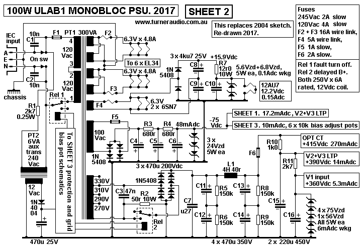
The power supply has all solid state rectifiers. A CLC filter
ensures low B+ rail noise and 50r x 10W limits
the initial peak charge currents into the 235uF + 4H + 235uF to
allow a lower and more effective mains fuse
to be used.
DC is applied to V1 heaters and fixed grid bias and B+ supplied
to V1 is shunt regulated. The PT I wound
has 90mm stack of 38mm tongue wasteless E&I. The heater
windings are between first on mains winding and
following HT winding. There are 4 x 6.3V windings in one layer,
arranged to make a 12.6V winding with a CT which
is directly connected to the chassis. Therefore the heater
windings act as an electrostatic screen between mains
and all other following windings. There is an additional 6.3V
winding which I wound on last with the 100Vac bias
winding, and the that is used for 12.4Vdc for 12AU7 input tube
heaters.
Keener constructors could use the heater 4 x 6.3Vac windings to
power a full wave doubler rectifier to make 15.8Vdc
and then power 12AU7 plus the 6SN7 with dc heating current. As
it is shown, there wasn't much hum at the output
of these 100W amps.
My 2004 hand drawn schematic was not easy to read, and lacked
automatic shut down if one or more EL34 conducted
too much Idc. The original 2004 amps used a huge 1,500uF x
450Vdc cap for B+. Someone gave me a number of these
caps which had been used in 1980s university experiments for
some unknown purpose. Anyone building this schematic
now needs to have L, R and C which can all be easily sourced new
from suppliers. The CLC as I have it above will work
perfectly well with the amp. The choke should be at least 4H for
300mAdc, and 40r max, where it will drop 12Vdc, and
dissipate 3.6W.
SHEET 3 has a better protection schematic and delayed B+.
Fig 4. SHEET 3, 100W UL AB1 bias and
protection schematic.
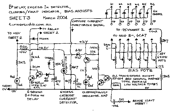
The fixed bias adjustment pots are arranged as shown to give
each tube a range of applied
grid bias between -33V and -48V. Each pot for each output tube
grid bias s adjusted so
0.5Vdc appears across the same tube's 10 ohm cathode resistor.
This indicates 50mA of idle current.
The process of setting the bias for the amp is repeated 3 times
after the amp has
warmed up because bias adjustments are interactive.
The circuit is actively protected against bias failure in one or
more tubes, or against
excessive and continued use with loads which are too low in
value.
Each cathode of each output tube is grounded through 10 ohms and
points K1 to K6 are
all fed to a common cathode monitoring signal path which has its
voltage reduced by the
R divider of 4k7 and 2k7 with a 220uF cap to remove unwanted ac
signals during operation.
Should one of more cathode dc currents rise to dangerous levels
for more than a couple
of seconds, the SCR will trip and the 16V relay supply will be
pulled to 0V since the
50 ohm 10W resistor is grounded at the relay end. If the SCR is
tripped the fault LED will turn on.
The same LED will flash if the amp clips
since the error signal from the output of V1 is fed through a
high resistance path to a
darlington pair of bjt driving a second gain bjt to turn on an
LED.
All the protection parts will fit on a small board under the
chassis and all can be easily
sourced at any electronic parts shops.
There is a 6 second delay for turn on of the B+.
Fig 5. Sheet 4, power vs load graph.
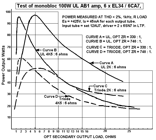
The graphs show maximum power levels at thd 2% just before
clipping with a range
of load values.
Curves A and B are for Ultralinear with either 2k : 6r0 load
match or 4.5k : 6r0.
Curves C and D are for Triode with either 2K : 6r0 or 4k5 : 6r0.
Any value of load along the RL bottom line can be chosen and the
output power
max can be seen on the curves.
Using the higher Z ratio on the OPT results in less maximum
output power for most
common loads between 4 and 8 ohms but the class A portion of
total power increases
and although the total AB power reduces the THD and output
impedance are both
much lower.
For example, if the OPT is set for a load match for 4k5 : 6 and
an 8 ohm speaker is
used, then the maximum UL power output only 52 watts, but it is
virtually all class A
and the THD will be about 1/2 that of 6 ohms.
Load matching is all very confusing to most people. A common
misunderstanding
is that the more ohms a speaker has, the more difficult it is to
drive. This comes from
knowing that common sense tells us carrying 10 bricks is more
difficult than carrying
1 brick.
But in fact, more ohms mean a less difficult load. Like so many
things in electronics, basic
common sense seems reversed to a novice. An Ohm is the unit of
resistance which is a
property of a substance to resist the flow of electrons. Where
you have 1Volt applied
across a length of wire, and there is 1 Amp of current, the wire
is said to have resistance
= 1 ohm. Ohm's Law is expressed in a formula, R = V / I , ie,
Resistance = Voltage / Current.
Power is the heat liberated in the resistance due to current
flow. It is most simply calculated
as P in Watts = Volts x Amps, ie, P = V x I. To make a
resistance get hot, you must generate
electrical power. The more power you want in a resistance, the
harder it is to generate
that power. The lower the ohms, the higher the current flow. The
higher the current flow,
the higher the power. and it applies to speakers. As speaker
ohms are reduced, the current
increases and the generator must be able to provide the correct
range of current and voltage.
So an amp is like a generator. It may be happy to make 16Vrms
for an 8 ohm speaker to make
2Amps of current and give 32W of power. But if 2 ohms is used
instead of 8 ohms,
the amp may not be able to make more than 3Amps, and you get
only 6Vrms, and 18Watts
of power, with high THD and tubes run too hot.
If you have 16 ohms, the amp may make only 1Amp maximum, and
16Vrms, and 16Watts of
power. However, the THD will be very low, amp will run cooler,
and best music is heard.
If anyone cannot understand what Ohms are, they need to study
Ohm's Law and history of
knowledge about electricity. This might lead to more questions
about many other basics of
tube operation and load matching effects and distortions.
Books such as the 1955 4th Ed of Radiotron Designer's Handbook
is an excellent read,
or they might read my other pages on tube basics. EDUCATIONAL AND DIY.
Fig 6. Sheet 5, 100W UL AB1 THD figures for two amps.
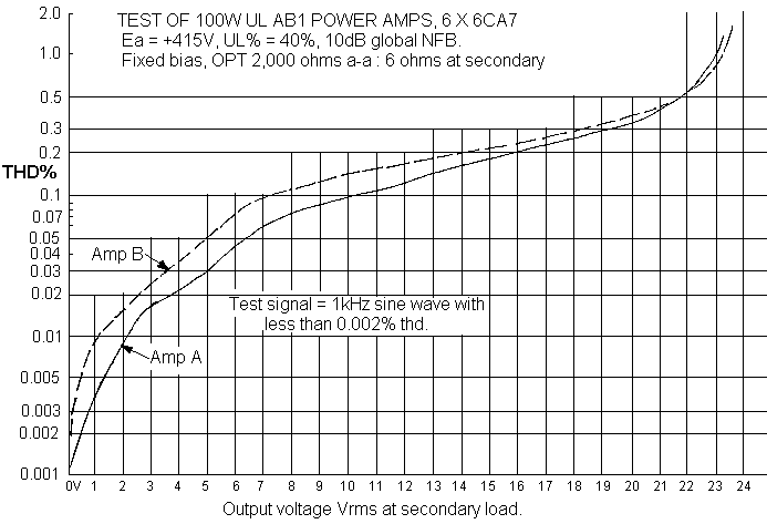
The graphs of total harmonic distortion, thd, are for one pair
of 100 Watt tube amps
with identical schematics. There are two curves for amps A and B
and there is up to 7dB
difference between THD at below 1Watt.
The graphs were made during completion work on the two amps. The
voltage scale is
linear and the THD scale is *logarithmic* to display small
quantities of THD more easily.
The amp A had the highest THD which is listed below with power
levels
and what would be SPLs using average modern speakers of 6 ohms
and
90dB/W/M :-
1 watt , 2.45vrms, 0.02%, 90dB SPL,
2 watts, 3.46Vrms, 0.03%, 93dB SPL,
4 watts, 4.89Vrms, 0.047%, 96dB SPL,
8 watts, 6.93Vrms, 0.09%, 99dB SPL,
16 watts, 9.8Vrms, 0.15%, 102dB SPL,
32 watts, 13.8Vrms, 0.20%, 105dB SPL,
64 watts, 19.6Vrms, 0.37%, 108dB SPL,
88 watts, 23.0Vrms, 1.0% 109dB SPL, :- It is so loud, it wakes
the dead.
Like nearly all amps the fidelity increases with a higher load
value but with a reduction of
maximum output power. Most people will find that with two
amplifiers average levels of 1/2 a Watt
from each will produce SPLs of 88 dB approximately although
peaks in drumbeats and transients
will go a lot higher but these will be very easily dealt with by
these amps.
The average level for most loud music in a domestic situation is
88db for men,
and 84dB for women and that includes both channels, so indeed
these amps have quite
enough power even for teenagers who like bass boosting if
possible in the preamp.
( OK, you have a killer teenager?... I don't want to know..)
Much is said about tube amp distortions spoiling performances
but let's get this into
perspective. If the speaker voltage is 5Vrms at 4 Watts of
level, then the THD = 0.05%.
Therefore the actual distortion voltage within the signal is
0.0025Vrms, and would be very
difficult to hear from across a room with speakers rated for
87dB/W/M, because the
distortion voltage alone gives 1 micro Watt of power, which
gives an SPL that is 60dB
below the 4 watt level of 93dB, so the distortion produces an
SPL at 33 dB which would
be below the sound level of heartbeats, breathing, and natural
background sound levels.
The THD spectral voltages in tube amps such as these at low
levels up to 4 Watts is usually
a mixture of predominantly 2H and 3H with other 4H, 5H, 6H, 7H,
8H, 9H etc all at least
12dB below the combined levels of 2H and 3H indicated on the
above graphs.
Either 2H or 3H harmonic may be greater at low levels because
the 2H at low levels varies
because of unavoidable slight unbalance in the 2H currents in
each half of the PP output
circuit because the 2H currents in each 1/2 of the PP circuit
are slightly different in level,
thus never completely cancelling as a result of push pull
action.
There are slight differences in the "matched" output tubes used
in the output stage and
driver stages. Plus the input stage produces some 2H since it is
a single ended triode stage.
The 2H content is the main reason for the differences between
the two amps' THD.
But at high output levels the THD of the pair of amps becomes
nearly equal and mainly 3H.
The 2H at low levels can be minimized by placing tubes in either
side of the PP circuit
so that ac signal currents measured across the 10 ohm cathode
resistors for each side
have equal totals, or as close as one can get, and this is a
very tedious thing to do and to
monitor with a distortion meter.
Unfortunately, this needs some technical expertise to achieve,
and usually does not lead
to any betterment of the music.
Triode operation was tested but very little differences with THD
were recorded at the same
low levels. Changing from UL to triode operation means the total
circuit gain is reduced
about 4 db. Therefore the amount of applied global NFB is also
reduced by the same amount.
With less global FB one would expect output resistance and
distortion to rise but the triode
connection itself gives a compensating reduction in THD and
output resistance so the
change from UL to triode does not require any change to the
global NFB network
resistances and the output impedance and THD will remain very
similar in either UL or triode.
These amps were prepared for someone with QUAD ESL63 and the
amount of NFB is
not high and could have been increased to levels used more
commonly by other makers
who might use say 20dB which would reduce all the above THD
figures by about 9dB,
or to 1/3 of the figures mentioned. I felt there was no need
since the output impedance
and THD was low enough.
There is nobody I know who can tell the difference between
triode and UL connected
output stages if the power levels are well away from clipping
and if the general total
levels of NFB are similar as I suggested above.
Back to education and DIY
Back to Index Page


