REFORMED
CARY 2A3i 10W CLASS AB AMP 2011.
Fig 1.

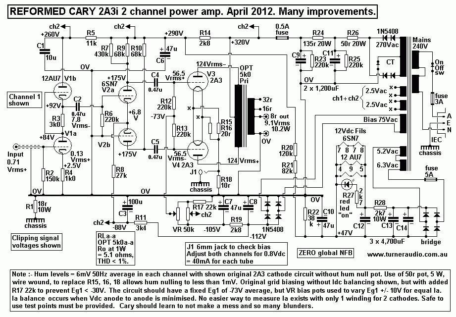
Fig 1 shows the slightly reformed Cary 2A3i and with re-labelled
OPT secondary output terminals which were originally meant
for 4r, 8r and 16r. But the OPT impedance ratio is far to low so
only 8r, 16r and 32r should be used as I show in Fig1.
Use of 4r speakers at original 4r outlet gives very poor results.
There is no applied GNFB and Po is mainly class AB at 10W at
onset of clipping with 8r0 output load where used as shown. Expect
THD = 4% at 10W, mainly 3H, 5H and 7H because of the
AB crossover distortion. At 1W expect 0.7% with mainly 3H, 5H and
2H.
Each 2A3 At idle point has Ea = +315Vdc, Iadc = 40mA, Pda = 12.6W.
Load line analysis for RCA 2A3 suggests following
possible results :-
Ra = 833r on Ra curve for Eg1 = 0V between 0.0mA and 150mA. For
maximum pure class A1 Po, RLa per 2A3 = 6k2.
Va at clipping = 180Vrms, giving 5.2W of audio Po.Therefore the
2A3 should have an OPT with ratio 12k4 : 4r, 8r, 16r.
For pure class A1 Va-a = 360V, giving 10.4W. 5% winding losses in
OPT will reduce the power produced by tubes to
about 10W at sec of OPT. The Ra at the idle Q point for each 2A3 =
1k0, so Ra-a = 2k0, so if the primary load = 12k4,
then damping factor = 12k4 / 2k0 = 6.2, and THD should be 1% at
10Watts and 0.25% at 1W. Anyone building an amp
with 2A3 and with Ea = +315V should have ZR = 12k0 : 4, 8, 16, so
that good pure class A is possible with most speaker
loads, and very little is to be gained by running the amp with a
lower RLa-a, say 5k0 when DF is halved and THD is doubled
while in class A and in AB its even worse, but that is just what
Cary have done, and its typical of so many amps made around
the world which appear to have been designed by accountants who
have forgotten how to make a good amp, or who ignore
those who really know.
Cary has OPT with 2k5 primary RLa-a when 4r, 8r, 16r, are used at
the available output terminals. To improve matters slightly,
minimum loads should be 8r, 16r. 32r.
One might hope the 10W produced by the Cary are the best available
10W ever known to music lovers. The 2A3 was
regarded as the best DH triode ever made. But I know the way the
tube works in the circuit is more important. For the best
from 2A3, it must be used for pure class A1 which requires
the OPT have an entirely different set of load matches to those
used by Cary.
A better load match exists for 4r speakers which isn't widely
known. Just consider the total sec turns = N turns, and a match
giving 5k0 : 32r. The 16r0 outlet has 0.707N turns, and 8r0 outlet
has 0.50N turns. Between 32r and 16r there are 0.293N,
giving 5k0 : 2r7, and between 16r0 and 8r0 there are 0.207N turns
giving 5k0 : 1r3. Using 4r0 between 32r0 and 16r0 gives
7k4 : 4r0, which is most useful to know if you insist on 4r0
speakers. The use of turns between 16r0 and 8r0 gives 14k6 : 4r0,
and you'd get about 7W of very pure class A. But where small
fractions of the available secondary turns are used, sec Rw
increases and primary losses decrease, giving a net increase of
total losses. HF extension may suffer because the P-S leakage
inductance increases as sec turns are reduced.
Cary do not offer any instruction about any of these issues. The
Cary biasing method of 2A3 is quite poor because there is only
ONE bias pot for each pair of 2A3, and bias current for both tubes
is measured at J1 and across R18. The reading for 80mAdc for
both tubes means J1 should read +0.8Vdc with bias correctly
adjusted. But the same Eg1 is applied to both 2A3, and unless they
are well matched there may be be 25mAdc in one 2A3 and 55mAdc in
the other and this tube would have Pda = 17.3W,
exceeding the allowable Pda of 15W, and the OPT will have a net
30mAdc flow in one direction across all OPT primary turns
thus causing core saturation from Idc because there is no air gap
in the PP OPT. Music become mud in this outcome, yet many so
called audiophiles will not hear any difference, but might see the
smoke rising from the amp, and smell the bad smell.
2A3, and its big brother, 300B do not like running too hot and are
more fragile than EL34 or KT88 etc. There is no way to
balance the Iadc of each 2A3 if they are not matched, yet quite
serviceable in every other way. I did very minimum re-engineering
to this amp because the owner did not want to spend much money.
Hum levels could be reduced if each 2A3 had its own individual
2.5Vdc cathode heating supply. Then each cathode circuit could
have its own current sensing resistance to allow use of a pair of
LEDs
to monitor Iadc in each 2A3. This means a single balance pot can
increase Eg1 of one 2A3 while decreasing Eg1 on the other until
balance is achieved. The total Idc of both 2A3 will remain little
changed. With so many varieties of 2A3 and brands, it may be
necessary for a second bias pot to adjust the total Iadc for both
2A3 equally, so the best arrangement has TWO 10k wire wound
pots, one for Iadc balance and the other for total Iadc. Iadc
balance can be set and monitored using a pair of LED as I have
installed into so many other amps. A number of other problems were
dealt with when I worked on the amp such as providing
a 0V buss with connection to the chassis via R1 18r. For those
wanting to build a better PP amp for 2A3, I have the schematic
they need.....
Fig 2

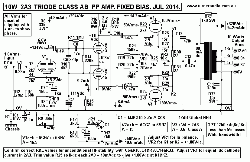
Fig 2 shows all anyone needs to do for PP 2A3 to get excellent
class A1 performance with fair performance in class AB1,
much assisted with fixed bias. After any DIYer builds this
schematic, he must bias the amp within 10 seconds of turn on.
Input signals must not be present. Before turn on, set both VR1
and VR2 at their centre positions. After turn on, adjust VR1
for equal Idc in each 2A3. This is easily done by measuring Vdc
between points K1 and K2 while turning VR1 to whatever
position is needed to get close to 0.0Vdc.
VR1 equalizes or balances Iadc of each 2A3. Then VR2 is turned so
that Vdc = 1.08Vdc between K1 and 0V or from
K2 to 0V, which indicates Iadc = 40mA in 27r.
VR2 alters the total Iadc of both 2A3. Following VR2 adjustment,
Vdc between K2 and K1 is re-measured and VR1 is
turned to get the lowest Vdc possible. After say 20 minutes, both
adjustments are repeated and their settings probably
will not need to change for months.
K1 and K2 may be taken to a balance indication and active
protection circuit on a small board using small discrete bjts,
and an SCR etc, similar in principle to many other amps I have
built and detailed at this website. The schematic allows
use of 6CG7 or 6SN7 for V1 SE triode input tube, and V2 LTP
driver.
6CG7 is mini nine pin and 6SN7 is octal. Both have the same
properties. For fixed bias with 2A3, the B+ to OPT CT should
not be higher than the +320Vdc. The 6CG7 used for V2 LTP requires
a higher B+ of about +400Vdc for optimal loading to
produce a large Vac swing at low THD for 2A3 grids of up to
60Vrms. But the B+ for OPT at +320Vdc is too low, and when
RC filtered by R32+C12, the B+ is only +294Vdc.
To obtain the extra Vdc required for a total of about +400Vdc, I
have used the -140Vdc B- rail which supplies the bias
balance network and constant current sink Q1.
There is an R divider with R15, R12, R13 between 0V and -140Vdc,
to bias the Q1 base at -121Vdc, and bias both
grids of V2 at -111Vdc. So the cathodes of V2 are at -103Vdc. V2
B+ = 294V + 103V = +397, and maximum Va-a
between V2 anodes = 190Vrms.
Other V1 tubes could be used, such as 6DJ8, with more gain than
6CG7. For V2, a better tube is 12BH7, or 6BL7,
with -3dB less gain than 6CG7 / 6SN7. But the 6CG7 and 6SN7 are
plentiful and will work OK and give fabulous music.
12AU7 could also be used for V1 and V2 which would reduce the open
loop gain by -6dB and reduce the amount of
applied GNFB.
With such changes, the biasing Rk resistance for V1 must be
changed to get the correct Ea, and pin outs for heater voltages.
An interesting combination will be with V1 12AU7 and V2 ECC99. For
those wanting cathode biasing with 2A3, they will
need B+ at CT = +390Vdc.
The VR1 and VR2 bias adjust pots may be deleted, and R&C
cathode bias networks to each 2A3 will be 1k8 10W
plus 470uF 250Vdc rated. The rest of the schematic will be
unchanged, and the B+ applied to V1&V2 will rise to about
+360Vdc. The -140Vdc rail is retained, and the biasing of V2 grids
remains at -111Vdc, and the B+ for V2 will be +464Vdc.
The Q1 CCS current may be increased to about 11mAdc, by changing
R17 to 1k8. This will improve the general operation of
V2 triodes. Those wanting to build 10W amps with 2A3 should know
how to design and build a suitable PSU to provide all B+
or B- rails plus DC heater supplies. They will find it takes far
more cost and effort to make 10Watts with 2A3 than to make 10W
using a pair of EL84 with ultralinear OPT taps. However, a well
made class A triode amp is still an excellent option.
Back to re-engineered amps
directory
Back to Index 
