INTEGRATED
50-50
STEREO AMP.
Latest update 2017. There is more information here now for the
serious DIYer.
Building an amp like this involves huge amount of time, a history
of finishing projects,
practised skills, good tool set, a secure place to work with good
lighting, and a roof that does
not leak, and a patient wife.
Picture 1. Integrated 5050. The first 5050 amp made
in 2000.
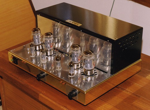
This 5050 was custom was custom built in 2000 for a client in
Victoria.
The chassis was made using a 55mm high brass channel brazed at
each corner, with two top plates,
one of aluminium for tubes and the other steel for the bottom of a
box for a heavy 6Kg E+I PT and
two C-cored OPTs each 5Kg. The bottom plate is perforated steel to
allow ventilation up through
bottom plate and up through sub chassis volume and up past the the
output tubes.
The single rear box is a cover over open-frame transformers and is
painted aluminium. There is a
perforated steel cover which screws down over the tubes but is not
shown. The amp front panel
has red / green LED beside rocker on-off switch and two pairs of
Red LED which indicate the Idc
balance of the two KT88 used in each of 2 x 50W audio power amps.
There are two adjust screws
on top of chassis in front of the two outermost KT88 to allow
manual balancing of Idc.
The centre knob is a volume control aka level control aka gain
control, and left side knob operates
a 5-way rotary source select switch.
The front row of 4 smaller tubes are 4 x 6CG7, each with 2 triodes
for signal handling.
One of the central 6CG7 has two triodes and each is used for
simple line level preamp ahead of the
50k log gain control pot. The other central 6CG7 has two triodes
with each used for the input tube
which feeds a pair of triodes in each of the outer 2 x 6CG7. Each
outer 6CG7 drives the output tubes.
The KT88 or 6550 connect to a wide bandwidth output transformer to
transform the anode power to
be suitable for a range of selectable speaker impedances above
3r0. The OPT has screen taps on its
primary for 43% Ultralinear operation.
Power maximum at onset of clipping with pure resistance load and
1kHz sine wave :-
4r0, 54W AB1 with first 6.6W class A.
6r0, 46W AB1 with first 10.0W class A.
8r0, 36W AB1 with first 13.3W class A.
12r0, 25W AB1 with first 20.0W class A.
16r0, 23.0W of only pure class A.
Weight = about 30 Kg.
Output tubes = any brand of KT88, 6550 and Sovtek KT88 shown in
picture. KT90 and KT120 may be
used without any circuit change, but may have higher idle Idc and
give higher initial class A power.
Input tubes = 4 x 6CG7 in picture. ( Later versions of this amp
used 6 x 6CG7 ). 6 x 6SN7 are also ideal.
At bottom of page I have a version of the amp with 2 x 6CG7
and 2 x ECC99, now well regarded.
Bandwidth at 40W into 6r0, 18 Hz to 68 kHz.
THD at 40W, less than 0.2%,
THD at 3W, less than 0.05%,
Output impedance less than 0.3r, Damping Factor = 20.
16 dB global NFB.
Stability is unconditional, and the amp can be used with any type
of speaker load, and it does not
need to have a load connected while turned on.
Fixed bias is used with full active protection and bias
balance red LED indicators are mounted
for easy viewing on the front panel.
When both pairs of LED are not glowing, the idle Idc in each pair
of KT88 are within +/- 3mAdc of
each other and both the bias balance adjust pots are set
correctly. A small amount of turn of bias
adjust pots will make an LED turn on, so as long as both pairs of
red LED remain not glowing,
the KT88 tubes are working OK.
After turn on, one or more of the 4 LEDs may flash during warm up,
but then not glow after 30 seconds.
At turn on, the green LED under the red LED near on-off switch
should turn on and stay alight.
If the green LED turns off and red LED turns on, the internal
protection circuit has detected a problem
and turned off the large mains power transformer and all tubes
will go cold without any damage to
power supply or to output transformer. The amp may be re-set by
turning mains switch off, then on,
and if amp turns off again it tells an owner something is wrong
and needs someone technical to look
at it.
Many owners thanked me for including active protection, and I was
the only one who ever did.
Fig 1. Schematic of one channel of 50W amp with
improvements in 2006, 2012, 2017.
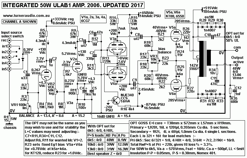
Tubes are numbered V1a, V2a, V3a, V4a, V5a, V6a because this
is Channel A.
Channel B has V1b V2b etc, and the two triodes within a 6CG7 are
used for V1a+b and V2a+b.
The pictured amp from 2000 had V3 and V4 each being one of the
triodes within a single 6CG7.
One customer who bought a 5050 in about 2003 used his amp daily or
nightly for 5 hours, and after
4 years one 6550 began to trigger the protection circuit, so I was
able to see how the other 3 x 6550
were wearing, and I found bias Vdc was a few Vdc higher than it
should have been due to the
phenomena of grids becoming more positive than the -Vdc supply. In
2000, I used 220k for R19+R20
but when tubes age, they develop a tiny Idc input current the grid
more positive than the Eg1 bias
source at top and bottom of VR3
From my study of vacuum tubes, the "positive grid syndrome" is
caused by positive gas ions which
are not all absorbed by gettering which has become less able to
absorb gas molecules. The +ions
gather at the grid, thus making it very slightly like an anode, so
it attracts electrons which we might
assume are re-emitted to to the electron flow rushing past grid
from cathode to anode. New tubes
usually have a very slightly negative grid, ie, electrons flow
from grid to bias -Vdc.
In the amp I serviced, I changed R19+R20 to 100k, reduced R14+R15
to 39k, and increased Iadc
in V3+V4, and this made the next set of tubes last longer. The
positive grid syndrome affects many
old tubes, and in power tubes is increases idle Pda which raises
temperature which makes the
problem worse, so its an unwanted positive FB function. For 6550
or KT88, Iadc increases by
grid increase x gm g1, so for +3Vdc, expect Ia to increase 15mAdc
which may make total Ikdc =
52mAdc + 15mAdc = 67mAdc, and Pda at idle = 35W, and the tubes are
feeling too HOT.
The benefit of fixed bias is less THD for high power, and
no wasted heat in cathode bias resistors.
But there is no self regulation function which is a feature of
cathode biasing.
Biasing? WTF is that? Nearly every power tube needs to have
its grid Vdc less than the cathode Vdc
or else far too much Idc will flow in the tube at idle, so it gets
too hot. The grid Vdc should not be too
much lower than cathode Vdc, or tube runs too cool, and there's
high THD.
So grid Vdc has to be Just Right, and for KT88 with +500Vdc at
anode and screen, the grid Vdc
needs to be about -60Vdc below anode Vdc to get Iadc + Ig2 =
52mAdc. The act of "biasing an amp"
means adjusting the grid Vdc to achieve the wanted 52mAdc.
So where an amp has "fixed bias" it means an owner will
have to use a screw driver to turn
something on the chassis that is like a slotted screw head, AND
watch a volt meter reading.
Its the kind of very simple technical activity which maybe 33% of
owners manage to do very badly,
or if they do it right, they don't do it again soon enough and a
tube overheats and KT88 are not cheap,
or they forget what is involved, or they sell the amp, and the
next owner is even more dumb, and the
owner manual has been lost.
95% of problems I have had to fix in tube amps were due to bad
biasing.
What could I do about the problem with owners? I found I
could set the bias Vdc correctly for
both output tubes when I built the amp, and provide ONE adjust
screw for the two tubes in each
channel, and a pair of red LED near the 2 tubes so that the screw
is turned in one direction of the
other until both remain unlit. No volt meter needed, and only one
thing to remember - turn each
screw so all LED do not turn on. In some amps the adjust screw was
at front panel and a small
kitchen knife could be used, because not all ppl have a screw
driver in their house.
The "screw head" to be adjusted was a 6.3mm dia shaft of a 10k
wire would pot, VR3 in Fig 1.
If VR3 is turned one way, Vdc for one KT88 grid becomes more
negative while the other KT88 grid
becomes more positive, and the latter will cause an LED to turn
on. If the screw is turned the other
way, the LED will turn off, but the other may turn on. But there
will be a position of the adjust screw
where both LED remain off, and this is within a range of maybe 1/5
if the maximum turn of about 270
degrees of total turn for the pot. With both LEDS off, the Idle
cathode Idc will be found to be close
to equal, so say 51mAdc and 53mAdc ie, the difference in Ikdc is
less than 4%, and quite OK.
So the adjust screw is an Idc balancing method.
If the Vdc at each grid was measured, you may find one KT88 has
-62Vdc, and the other -58Vdc.
This unequal -Vdc bias is quite OK because equal Idc is wanted,
and not all tubes require the same
grid bias for a given Idc.
As the tubes age, the Idc varies and one LED may turn on, and a
slight turn of adjust screw usually
fixes the problem for the next 6 months. There will be a time
where there's not enough turn available
to keep both LED unlit. This means one tube has become sick, and
needs replacement, and maybe
the other 3 are also beginning to get sick and the Ikdc of a pair
of tubes is only gained by screw
turned near one end of its possible range of turn.
The positive grid syndrome in old but serviceable tubes can make
trying to balance Ikdc of a pair of
tubes more difficult, and when balance is gained, the Ikdc of both
may be equal, but both a bit too
high. Well, that does not matter too much unless Ikdc begins to
increase too much, and if Ikdc reaches
say twice the idle Ikdc, 104mAdc instead of 52mAdc, the tube Pda
has become 52W, and the anode
may glow a bit red. It is time to replace the tube. But if that is
ignored, and the tube Ikdc goes higher,
the amp turns itself off internally, using a circuit which turns
the main power transformer off,
turns off green "on" LED and turns on a red Fault LED.
My system works better than having say 200mA slow fuses between
each cathode and 0V.
Owners will insert a 2A fuse because that's all the shop had, or
they wrap aluminium foil around
the blown fuse. There are no limits to clever stupidity. So then
there is no protection against
overheating of a primary winding of OPT, and most owners are not
clever enough to disable
the protection system.
As the years roll by, output tubes get age related illnesses and
while sitting in an amp after
5 years+ they can develop positive grid syndrome where positive
ions collect at grid and it
attracts electrons to itself and these form a small current and
the normal -Vdc at grid becomes
more positive, perhaps by a volt or more, thus increasing the idle
anode-cathode Idc.
The tube gets hotter, and that increases the effect, so it is a
positive feedback action that
only hastens a tube towards its death by overheating.
In Fig 1, I have 68k grid biasing resistors R19 and R20. I have
known owners to get extra years
of tube life if the biasing R is reduced from common values of
220k to 680k used in many amps.
But amp companies owned shares in tube making companies who made
more dough if tubes
wore out sooner rather than later.
In Fig 1, see V3a, a paralleled 6CG7. The dc carrying RL is R14
33k. The anode load for parallel
6CG7 = 33k // 68k + 5k0 of VR3. So total anode load RLa = 22.7k,
and anode resistance Ra is
about 6k5, so ratio of RLa : Ra = 3.5 : 1 which allows the V3a and
V3b to operate with very low
THD and IMD and to get widest possible Va swing well above the
maximum 40Vrms for clipping.
The paralleled 6CG7 acts like a single triode, µ = 20, Ra = 6k5 at
7mAdc, and gain just over 15.
The parallel triodes give better sonic dynamics.
Integrated input :-
The input signal is selected by the rotary wafer input switch and
is attenuated by about 4 dB by the C1,
R2, R3, and VR1 100k linear pot to get equal audio levels at each
speaker, and best stereo imaging.
The audio balance control is not needed by true Hi-Fi ppl, and
there was not one in original 5050 from 2000.
Balance controls were used in early days of so called hi-fi to
compensate for poor dual volume pots which
did not have equal logarithmic resistance change. Many ppl
resented the idea of ideal speaker placement
for good imaging, and speakers were placed where a wife tolerated
them, so the balance control tried to
make the balance better, but imaging was much worse with one
speaker at 2 metres and other at 4 meters
away. Serious Hi-Fi ppl have at least Alps Black volume pots, (
27mm square body ) or have switched
attenuators from DACT, and I understand why so many remain
unmarried. Music comes first, OK.
V1 is 1/2 a 6CG7 working as a simple SET preamp stage, gain
= about 8.6, and drives 1/2 a dual log 50k
Alps Black volume control pot. The total anode load is about 24k,
a bit low, but the unbypassed R6 1k0
gives about 4dB local current FB to reduce gain from 14 to 8.6.
With a balance control shown, if a CD
player makes 1.4Vrms max, then V1 Vg = 0.67Vrms which is amplified
to Va = 5.8Vrms, and with volume
at 12 o'clock, pot output = 0.58Vrms, enough level to make 3W to
4r0, and if speakers have sensitivity
= 87dB/W, then you get 92dB SPL at each speaker and 95dB total,
and music would be very loud.
Most ppl enjoy average SPL levels up to 85dB average, with music
peaks going much higher.
The power amp needs 2.3Vrms input for clipping at 50W, and only
0.23Vrms for 0.5W at each speaker
which is usually enough, most of the time.
For old FM tuners which may have max output = 0.2Vrms, the volume
control can be turned up to get
good music.
V2 is 1/2 6CG7 and first triode of the power amp and is a
SET stage acting as a differential amplifier to
accept the signal input at its grid and the feedback signal at its
cathode, so the difference between the
input and feedback signals form the Vg-k between grid and cathode.
Gain of V2 is above 15.
V2 anode Va drives LF and HF gain shelving R+C networks to shape
the open loop frequency response
to ensure unconditional stability. All amplifiers are bandwidth
limited devices. The OPT and C+R coupled
tubes limit bandwidth without any GNFB from about 10Hz to 50kHz
with a good OPT. The tubes have
more bandwidth than OPT, and at ends of the bandwidth there is a
lot of phase shift which will cause
oscillation no matter how fast the time constants are for HF, or
how slow for LF. The GNFB need only
be applied to its maximum amount between 20Hz and about 15kHz.
Below and above this band, the
gain of the tubes needs to be reduced by up to -20dB. "Open loop
gain shelving" R+C networks
between V2 and V3 prevent the amp having a high amount of NFB at F
where no sane person should
want it.
C3, C6, R12, and R13 shelves the LF gain and phase shift at below
20Hz.
3 LF poles are created, -3dB at 15Hz, -12dB at 3.4Hz, flat shelf
at -15dB, then ultimate LF pole at
0.28Hz.
It can be shown by experiment and Bode / Nyquist theory that the
network with GNFB makes LF
oscillation impossible, and the amp F response below 20Hz has no
peaks.
C7+R11 form a Zobel network which works with the 8k0 for V2 Rout
to give HF -3dB pole at 43kHz,
then -7dB pole at 140kHz, then flat shelf at -10dB, then ultimate
-13dB pole above 500kHz.
Similarly, this can be shown to help prevent HF oscillations above
50kHz, and there are no peaks
in HF response.
The LF and HF networks are also known as critical damping
components and are chosen to best
suit the Lp and LL and Ca-a characteristics of the OPT combined
with the effective Rout of tube
stages with shunt their limited bandwidth.
The 5050 had additional stability networks, Zobel R34+C11
at output, and C12 across R35.
Warning! Others building this kind of amp
won't have OPTs equal to the OPT used here.
They may choose slightly different tube types, so that values may
need adjustment for C7+R11,
R34+C11, and C12.
Therefore this schematic is a guide only for general
method. Using wrong R+C in stability
networks can cause oscillations at LF or HF or both.
V3 and V4 form a differential amp with commoned
cathodes and CCS to a negative B- rail.
This means Va at anodes can only be two equal amplitude phases and
only produced by the
difference between the two grid input Vac. In this case, input is
to V3 grid only from V2 anode.
V4 grid is taken to 0V. This "differential amp" is also called a
"long tailed pair", or LTP.
V3+V4 have exactly equal resistance anode loads. Both cathodes are
commoned and their
current flows to a Constant Current Sink, CCS, which is the
collector of MJE340 set up to make
it act like a resistance of approximately 8 megohms, so that a
2.5Vac change at cathodes produces
Iac change = 0.31uA.
The Va produced by V3+V4 can be up to about 85Vrms in two phases,
but only about 42Vrms
is needed to drive the V5+V6 output grids. The gain of each of
V3+V4 is about 15.4, so 5.2Vrms
between each grid is needed. With V4 grid at 0V the 5.2Vrms is
applied to V3 grid, and you will
find about 2.6Vrms at the commoned cathodes.
The mysterious MJE340 is a general purpose bjt found in
1,001 solid state power amplifiers
used to drive output transistors. It easily withstands Vce = 300V,
and at 25C and with Ic = 14mAdc,
base input Idc = 0.1, if Hfe = 140. No data sheets tells anyone
the base transconductance Gm
or resistance between collector and emitter, Rc.
I picked a random sample of MJE340 from my parts bin and set it up
for a common emitter gain
stage with Re 1k0, bypassed with 1,000uF, RLc 3.05k, and drove the
base with a low Z source
< 100r, and measured the gains for two different RLc. I found
Rc above 50k,
and gm = 0.43Amps / V, Hfe = 141, Rb = 328r.
Fig 2. MJE340, basic model.
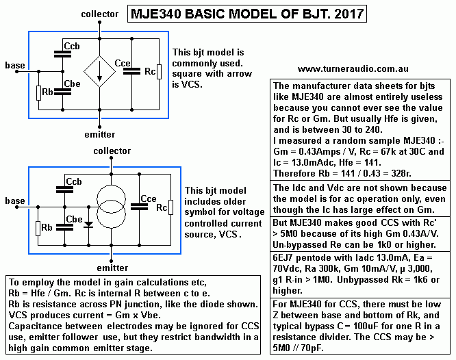
I don't expect too many people to understand anything in Fig 2.
But then after you have spent a few hundred hours studying the
basics about how bjts work,
maybe you will find a light turns on :-)
If the above remains a Miss Terrey, maybe this will help on just
how a Constant Current
Sink works :-
Fig 3. MJE340 CCS.
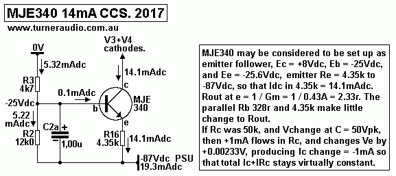
MJE340 CCS in Fig 3 is explained, but I think its operation
is still not obvious because of the
hidden internal resistances of Rc = 50k+ and Rb = Hfe / Gm
= 328r within the MJE340.
But the Rout at emitter = 1 / Gm = 1 / 0.43A = 2.3258r,
and this is parallel to Rb 328r and
Re 4.35k so Rout could be 2.308r. The ac model shows Rc which I
estimated = 67k.
if Vc increases +67V, you'd expect +1mApk in 67k which raises Ve
by +0.00208V, which
produces Ic change = - 0.43A x 0.00208V = - 0.992mA, slightly less
than in Rc, so although Vc
change is a lot, the total I change in anything causing Vc change
is extremely low, ie,
the resistance looking into collector terminal is extremely high.
You may try to measure it with
Vac applied though an series R but remember that Cc-e may be 100pF
with Xc = 4M0 400Hz,
this is less than the expected effective Rc with a large Re
resistance.
The bjt has has no active signal controlling effect, and probably
improves the music.
I could have used a 6EJ7 pentode for this CCS but there is no need
since the tube would have
no other function than providing a high ac impedance at the common
cathodes, and the MJE340
works better than pentode to act as a perfect slave to the two
triodes.
In 5050 for 2000, V3+V4 were each 1/2 6CG7.
, R14+R15 were 47k, and C coupled grid bias R19+R20
were 220k. This meant anode load RLa for each triode was 38k, over
3 times Ra and this gave good
enough drive performance with low THD.
In near new output tubes, grids are slightly more negative than
the Eg1 bias at ends of VR3, and it is
because vacuum is nearly perfect, and you may see a feint dark
blue glow at night.
But as KT88 or 6550 age, O2 or N2 gas is released by metals or it
seeps past the seals around lead
in wires to glass, and most is absorbed by the silver coloured
gettering which is pure barium or
something else able to instantly be oxidised by oxygen, or maybe
combine with nitrogen, or any
other gas.
After a few years, the gettering discolours or just seems to
vanish, because its becoming fully
combined with gases to form oxides, nitrides etc. The tube then
has positive gas ions that linger
without being quickly absorbed by gettering, and some gather at
the grid, making it slightly positive,
so electrons flow into the grid, and generate Vdc that is more
positive than the grid bias supply.
The slightly positive grid still works well, but the positive Vdc
usually increases slowly over a year
or two.
I've seen KT66 in Quad-II amps with +1Vdc across their 680k
bias resistors soon after turn on.
When warmed up, there may be +5Vdc after 30 minutes. There is a
tiny Idc flow = 7.3uA.
The +Vdc increase is due to grid becoming slightly positive.
Consider V1 with the problem and V2 is OK. Suppose V1 Eg1
increases +4.5Vdc. Iadc increases
so the Vdc at common Rk 180r, rises about +1Vdc, and IRk change =
+5.6mAdc. But V2 Iadc
reduces about 2.2mA, so the current increase in V1 = 2.2mA + 5.6mA
= +7.8mA and Vg-k change
is = +3.5dc and so Vg1 - 0V change must be +4.5Vdc.
Thus if idle cathode Idc in V1 and V2 is each 65mAdc at idle, if
V1 has +4.5Vdc at its grid,
Iadc in V1 = 72.8mAdc, and V2 has 62.8mA, so there is a 10 mAdc
imbalance.
This seriously affects the OPT which develops unbalanced Idc, so
core is partially dc magnetised.
It is not unusual the THD is 10 times what it should be, even with
the high amount of NFB applied.
As time goes by, the tube temperature rises and the positive grid
syndrome gets worse, and one
anode begins to glow cherry red and sound becomes bad, but the
ageing owners became less
perceptive and didn't notice the bad sound of one channel and
finally one KT66 completely loses
its grid control of Iadc, and its Iadc rises to say 250mAdc, which
then can cause OPT damage,
and damage to GZ32 and PT, all before the mains fuse blew.
Old amps need TLC; you cannot easily buy spare parts for them any
more. They usually need
a LOWER mains fuse value than fitted originally because none of
these dear old amps have any
active inbuilt protection mechanisms.
Quad-II and many other amp makers in 1960 insisted on having a
high initial amount of class A
power so the tubes idle Pda was often very close the maximum Pda
rating. KT66 in Quad-II had
Ea 320Vdc, Iadc + Ig2 = 70mAdc total for Pda+Pdg2 = 22.4W. The
tubes always ran HOT
when turned on. The higher the temperature, the shorter the tube
life.
Many old push-pull amps had high initial class A and not much
class AB because that allows for
an atrocious quality PSU to still provide hi-fi performance. Class
AB requires better PSU than
Quad of Leak etc were prepared to supply, because for 20 years
after WW2, nobody had the
money to pay for anything better.
Recommended Rg for USA made 6550 was 50k for fixed bias. I
have never been sure if this
applies to Russian 6550 or KT88, which appear to have the same
internal metalwork and to give
the same electronic measurements. But I found positive grids could
occur too soon where Rg = 220k,
even with idle Pda at 25W, much less than max Pda rating of 42W. I
did find Russian 6550 and KT88
aged no faster than GE6550-A, which was considered the Gold
Standard for 6550.
I found Russian output tubes aged most slowly when idle Pda <
16W. They can give excellent sound
where there was local cathode feedback, CFB, and where the OPT has
wide bandwidth and the PSU
has ideal engineering.
So by 2001, I began to use grid bias R = 120k which seemed to
lengthen tube life where idle Pda
was low, and where idle Pda was higher for class A I used 68k,
which adds years to tube life.
V3+4 in original 5050 were each 1/2 6CG7. R19+R20 = 220k,
R14+R15 = 47k, total RLa = 39k,
B+ = +450Vdc, Ea = +250Vdc, Iadc = 4.0mAdc.
Va max is about 100Vrms. Only 45Vrms is needed so 1/2 6CG7 will
drive output KT88 OK.
With R19+20 reduced from 220k to 68k, RLa = 28k, Va max is reduced
to 80Vrms, and THD is
slightly higher at all levels. IMHO, it is not ideal.
With parallel 6CG7 for each of V3+V4, R14+R15 can be 33k, and with
R19+R20 = 68k, same B+, Iadc
= 2 x 3.5mAdc = 7mAdc, Ea = +200Vdc, max Va = 87Vrms, due to grid
current at Ra diode line but
there's no THD due to cut off, and so the driver stage just works
better because each triode is loaded
with RLa = 44k and THD is lower, and I found the sound became more
dynamic, probably due to a
higher amount of available current to drive into output tube grid
capacitance.
The equal amplitude of Va at each V3 or V4 is solely due to equal
resistance loading. 1% metal film
resistors are cheap and getting equal Va is routinely easy.
Un-matched or different tube types could
be used for each V3 and V4 and Vac will still balance. 12AT7 and
12BH7 could be used with cathode
biasing adjusted to make Iadc equal. Va will remain equal, with
a is a slight increase of 2H.
With 2 x 6CG7 the 2H should be much less than the small amount of
3H.
1 x 12BH7 is a mighty tube for V3+4, and could be used
instead of the 2 x 6CG7 with no R load
change and same 14mAdc for CCS. The 12BH7 needs 6.3V x 0.6A
between pins 9 and 4+5 tied
together, so you cannot just plug in 12BH7 where there was 6CG7
without making a change to heater
wiring.
For 1/2 12BH7, Ra = 8k0 for 210V x 7mA, µ = 16, so gain with RLa
22k = 11.7, about -3dB less than
paralleled 6CG7 and it makes the same max Va, but with 12BH7, the
GNFB should be increased +3dB
so the amp would need about 3.2Vrms at input for clipping. This is
not a huge problem because V1+V2
will still have enough gain, and VR2 volume pot might need to be
turned up slightly.
( Further down this page I mention use of 1 x ECC99 for V3+V4.
)
In Fig 1, the biasing for output V6+V6 KT88 grids is via
R19, R20, 68k, which are fed about -60Vdc
from the adjustable network R17, R18, VR3 and R23. The bottom of
R17 and R18 connect to -87Vdc from
the PSU. I supplied these amps with bias network shown to give
above -60Vdc to grids with cathode Ikdc
at 50mAdc. VR3 is the only adjustment for each channel and it only
provides Idc balancing, so that one
KT88 may have -58Vdc at its grid, the other has -62Vdc, but Ikdc
for both = 48mAdc.
It is more important to have equal balanced Ikdc in each tube than
have an exact 50mAdc at each tube.
The idle Ikdc could vary + / - 15mAdc in both tubes without
causing a problem, but Ikdc must remain
equal for both.
The only bias adjustment for the owner for schematic in Fig
1 is to equalize the Idc of each output tube.
Each of the two VR3 is a 10k x 3W linear wire wound pot, 24mm dia,
6.3mm aluminium shaft. This bolts into
amp top plate with slotted shaft pointing up and only 6mm higher
than the holding nut, held tight with contact
glue wiped on the thread and body when assembled to prevent the
whole pot coming loose and turning
around. These adjust pots could be mounted for access at front
panel, but then prone to accidental movement,
or a child's experiment watching how the red LED can be turned on
and off.
The 5050 from 2000 had a steel cover with hexagonal pattern holes
each 8mm across and giving 70% open,
allowing tube inspection without removing cover, and allowing an
owner to adjust pots with flat blade screw
driver with 150mm shaft. The cover prevents tubes being pushed
over sideways during the OOPS moments
in an amp's life, and prevents a child touching the untouchable.
VR3 adjusts bias balance and does NOT change total of both
Iadc for the two KT88 or 6550.
With VR3 set for middle position, one or other LED may turn on,
showing Ikdc may be different by say 3mA.
The same - 60Vdc applied to each KT88 may give 50mAdc in one and
55mAdc in the other, but when VR3
is turned one way or other, both LEDs will be unlit for a small
amount of turn of the pot, showing Ikdc is
within +/- 3mAdc, and their average Ikdc = 53mAdc, so idle Pda+g2
= 26.5W = OK.
The -87Vdc rail is well filtered but not regulated. If
mains Vac rises from 240Vac to 255Vac which
I have sometimes measured, then B+ +515Vdc will rise to +546Vdc,
+6.2%. The -87Vdc rail should
move 6.2% to -92Vdc, and the -60Vdc moves to -63.7Vdc. The Ea rise
of +30Vdc may make Iadc
increase +20mAdc with regulated -Vdc for bias. But the extra
-3.7Vdc bias should reduce Ia by
Vg change x gm g1, and if gm = 5mA/V at idle, the bias change
reduces Ia by maybe -18.5mAdc.
Therefore Iadc increase is +1.5mAdc, and Pda moves from 25W with
240V mains to 27.8W, and the
tubes will easily survive this.
If mains reduces -6.2% to 225V, B+ becomes +483Vdc, and bias
change = +3.7Vdc, so Ea change
causes Ia change = 12.5mA, grid bias change causes Ia change =
+18.5mAdc, so final idle condition is
483Vdc x 56mAdc and Pda = 27W, also well tolerated.
To get the correct Iadc in both KT88 or 6550, DIYers should
adjust R23 ( 22k ) for Ikdc = 50mAdc in both
KT88 when mains = highest, so that when mains are lower, Ikdc is
unlikely to ever be higher. Pda + Pdg2
at idle may be less than 26.7W when mains and B+ is lower, and Pda
could reduce to 20W without any
bad side effects.
DIY constructors may like to add a VR4 10k0 wire-wound
linear pot in series with R23 = 18k,
and have three accessible sockets per channel, all to suit 2mm dia
for most DMM probes. Two yellow
sockets are connected to k5a, k6a, and a black for 0V, to allow
reading Vdc across R24 and R25, each
15r0, so that for 52mAdc, 0.78Vdc is measured between each
yellow socket to 0V black.
Between yellow to yellow adjust balance pot for 0.0Vdc to get
perfect Idc balance.
If VR4 is used, and both Vdc are not 0.78Vdc, then VR4 may be
adjusted until you get 2 x 0.78Vdc readings.
The 5050 from 2000 required no special tools except a flat
blade screw driver with long enough shaft to
adjust balance pots. It could be a chopstick with carved flat end.
It may become impossible to make one of the LED turn off no matter
which way the balance pot is turned.
This indicates there is a serious problem with one output tube
which has moved to an unsafe working
condition where it is too hot. But its also possible one output
has much reduced Ikdc, or has completely
stopped working. This is least likely, output tubes mostly give
trouble by conducting too much Idc as they
before having uncontrolled excessive Idc just before they die. So
the red balance LEDs indicate a fault
with one or more output tubes. Temporary glowing of one or other
LED may occur just after turn on or after
turn off, all because Ikdc is not equal during turn on and off, so
is OK. Any red LED indicates a fault
which may be caused by excessive music levels, or a shorted
speaker cable, or something else.
But all red LED should remain unlit for normal use. Only idiots
ignore a red glowing LED.
If any one of more output tube has twice normal idle Ikdc for
longer than 4 seconds, the amp automatically
turns itself off, but may be "reset" by turning power switch off,
the amp off, waiting 4 seconds, and turning
amp back on. The active protection schematic and fuller
description is below.
The "Ultralinear" OPT has 50% screen taps and has been much used
by many brands since about 1955
to much improve the linearity of beam tetrodes and pentodes. With
UL, THD spectra becomes more like
a triode with far less odd number H. The effective dynamic anode
resistance, Ra for each KT88 is reduced
from a typical 32k at idle for tetrode mode to about 3k0. The Ra-a
= 6k0, and with OPT 6k5 : 4r0, the Rout
at Sec = 1.85r. The GNFB will reduce this to much lower value to
get damping factor > 10.
Fig 4. Power supply for 5050.
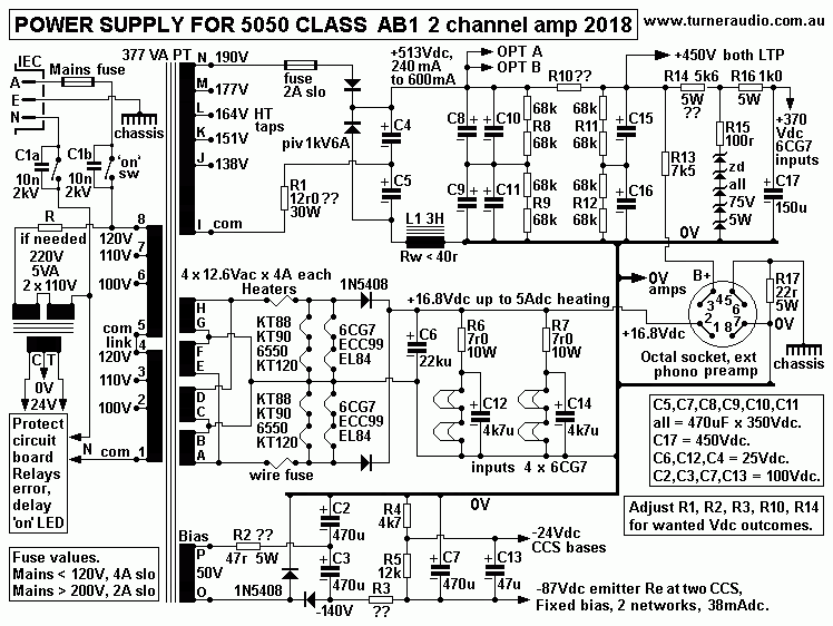
This PSU does not include regulator IC chips for Vdc and Idc for
power amp input triodes
and external preamp heaters.
At bottom of this page there is a winding diagram for the large
main PT.
Silicon rectifiers are used to give the best efficiency,
regulation, reliability, negligible heat,
ability to charge large value C with high peak charge currents of
several amps. Tube rectifiers
are a Royal PIA because their peak Iac during charging of C cannot
be more than 250mA.
Tube rectifiers create radiated heat on top of chassis, and need
maybe 15W just to heat
them up. The tube rectifiers cannot charge high value C more than
about 47uF, while Si diodes
with 6A rating and 1,000V for PIV seem almost indestructible
compared to a GZ34.
C-L-C filtering of B+ with Si diodes gives extremely low
hum levels.
The -87V and -25Vdc rails are RC filtered. V1+V2 may have have Idc
heaters, but need only
RC filters as shown.
V3, V4, V5, V6 have Iac heating. I show an octal socket for a
possible phono pre-amp. But most
ppl will use a separate phono amp with its own PSU.
T1 is the main large PT which has 377VA input for 343W
output, but with both channels
driven to clipping with low RL at output to make about 2 x 90W
with 2 pairs KT120, the power
input to PT can increase easily to 500VA, without smoke
production.
The PT copes OK making :-
Heaters. 2 x 12.6V phases at 6.6A = 167W
B+ . Voltage doubler rectifier makes +513Vdc x 323mAdc = 166W.
Bias B-. Voltage doubler rectifier makes -135Vdc, R+C filtered for
-87Vdc at 38mAdc and -25Vdc
T2 is a PT, 5VA, 220V or 110Vac : 12Vac to make +/- 16Vdc
rails to power active protection
and bias balance indication circuits.
Large PT has primaries adjustable for mains Vac = 240V, 230V 220V,
120V, 110V, 100V,
and this covers most countries.
T2 primary Vac can be 220V or 110V to suit above mains range of
Vac. I show R in series with
T2 primary, perhaps 820r would be OK to make primary = 220V with
240V mains. If mains = 220V,
primary is 200V, with sec = 11Vdc, which means Vdc to protect
circuit is low, but quite OK.
There is an octal socket at rear to supply B+ and heater power
to a tubed phono preamp.
Fig 5. Active protection, bias balance indicators.
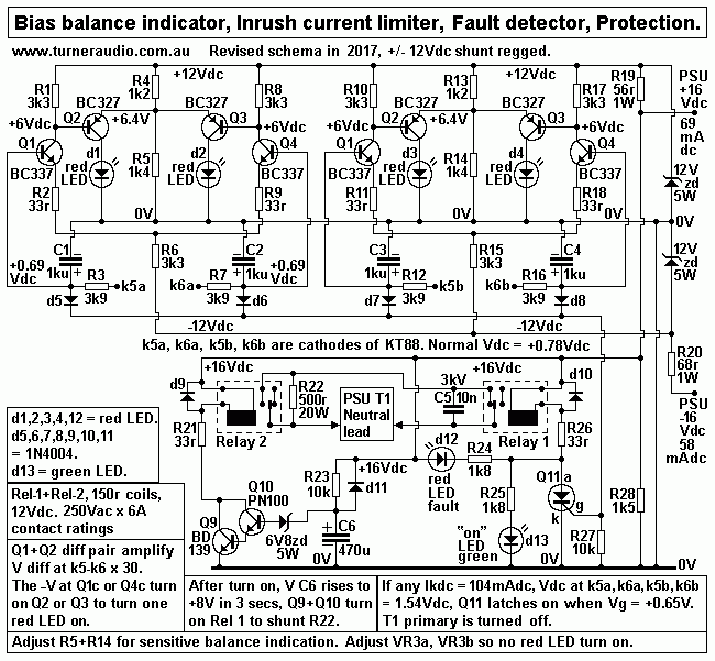
Fig 5 schematic is very much like the schematic I used for 5050
from 2000.
This protection schematic has been last revised in 2017, and has
more sensitivity to detect
excessive idle Ikdc with less sensitivity to high Ikdc due to
signal overload.
The Ikdc threshold for triggering Q11 SCR is 104mAdc.
Changes in Fig 1 :- R24+R25 KT88 cathode resistors are now 15r0,
not 10r0.
Changes in Fig 5 :- C1+2+3+4 = 1,000uF, 16V rated, R3+7+12+16 =
3k9.
There is no need to use 1/2 mains switch to commutate Q11a to 0V
when amp is turned off.
Green LED is operated by the protection circuit so if it lights
up, it means the amp is turned on
and the protection circuit is probably working.
Inrush current limiting.
When the amp is turned on, there is a high surge of Iac current
in mains primary for 3 reasons,
1. There is large Iac peak for first wave cycles in the PT
primary inductance.
2. Capacitors in B+ CLC require high Iac during first few wave
cycles to get energy store from
zero to high level.
3. Filament heaters have 1/2 their hot resistance when cold, and
then take about 15 seconds
to to heat up and have their resistance increase to give low
normal current.
Therefore all mains fuses should be slow blow types able to
withstand peak currents much higher
normal working currents for a short time, say 2 seconds.
See
http://ep-us.mersen.com/fileadmin/catalog/Literature/Application-Guidelines/electronic_fuse_facts_and_numbering_system.pdf
Fast blow fuses might blow in 0.1 seconds, Standard fuses in 1
second, Slow blow in 10 seconds,
but whatever mains fuse you choose you must aim to not have
nuisance blowings, and the fuse must
blow when Iac input rises 50% to 100%. A tube amp could have PT
using 377VA at primary input
for 240Vac, so Iac = 1.57A. But in class AB with B+ power
increasing 100%, the VA at input would
rise +55%, and fuse should blow at 3A input. It must be slow
type to allow for charging of B+ caps.
To avoid the problem of high inrush currents AND have a
sensitive fuse, when 5050 is turned on,
R22, 500r 20W is in series with mains Neutral wire to T1. The
mains Vac applied across T1 primary
slowly rises and when B+ reaches about +350Vdc, and at about 3
seconds after turn on, Relay 1
turns on to shunt the 500r, and there is a second inrush Iac
surge but much less than without the
500r, so the mains fuse value may be halved, and it becomes more
sensitive to faults within the amp.
Relay 1 is controlled by R23+C6, Q9+Q10 and 6.8V zener
diode. The R23 + C6 have time
constant = 4.7Secs, and Q9+Q10 turn on when Q10 base gets to
about +8Vdc. The diode across
C6 allows faster discharge of C6 so if amp is turned off, then
back on after say 4 seconds, the
delay circuit works again.
Excessive Ikdc protection.
Each KT88 is prone to excessive Idc flow which raises its Pda
and temperature to levels which
could cause damage to itself and OPT. If one of the 4 x KT88 has
too much Ikdc, the mains fuse
may not blow and I found the ONLY way to prevent impolite
pyrotechnical failures with smoke and
toxic fumes and co-lateral damage was with ACTIVE PROTECTION,
something impossible in
1960 because bjts were not available or reliable, and any
circuit for such protection was too
expensive or complex so that ppl were told to have their amps
serviced each year, just one more
thing ppl hated having to pay for.
Normal idle Ikdc at each KT88 cathode = 52mAdc which
flows through 15r0 x 5W to 0V.
Normal Ek at top 15r0 = 0.78Vdc. In Fig 5 above, if the Ikdc
increases to 104mAdc or one or more
KT88, the Ek increases to 1.56Vdc, enough to raise the raise the
Q11 SCR gate to +0.65Vdc when
it latches on, ie, stays turned on after 0.65V is applied to
gate. Q11 is like a switch, and turns on
Relay 2, which open the Neutral wire lead to one end of T1
primary, thus turning the amp off.
During normal operation for clipping levels at 60W to 6k5
: 4r0, max = 275mApk. The average Ikdc
increases to 107mA, and is nearly enough to cause Q11 to latch
on. But a sine wave signal is
needed to confirm this at any F above 20Hz. The Vac at 15r0 =
+4.125Vk, 0.0Vpk; there is no
negative Vpk. This Vac is filtered low by 3k9+1,000uF which has
a time constant of 3.9secs.
So if average Vk quickly moves up from normal +0.78Vdc to
+1.6Vdc, it should take about 3 time
constants or 12 seconds before the Vdc at top 1,000uF reaches
high enough to cause Q11 to
latch on. Music signals have constantly varying maximum peak
levels which rarely ever last for
more than 3 seconds at clipping levels, so normal music will not
cause the protection circuit
to work.
However, if there is a shorted speaker lead or very high
level used with a 2r0 speaker connected
to OPT set for 6k5 : 4r0, the max Ia can reach 500mApk, and be
square wave, so average would
be 250mA, generating an average of 3.75Vdc at 15r0, so that the
Q11 is soon latched on, and so
there is protection against use of low output loads which is the
cause of many amp failures if the
high level is maintained. Tubes can withstand the overload for
maybe 30 seconds, but many solid
state amps will fuse their output transistors within 3 seconds;
I repaired countless SS amps where
the overload protection circuit just did not work against
someone using a damaged speaker with
low Z, or there was a short circuit in cables to speakers.
But I also occasionally repaired tube amps with the same problem
of having been used with a
damaged speaker. Quad-II amps used with faulty 57ESL panel
speakers which have an arcing
panel will cause KT66 to overheat, PT to overheat and for damage
to occur, but the mains fuse
does not blow.
Each KT88 cathode has its own network with 15r0, 3k9 and
1,000uF. d5,d6,d7,d8 connect tops of
4 x 1,000uF to one point, and this arrangement means the Q11 SCR
gate reacts to the KT88 which
produces the highest Ikdc at its 15r0. The most common problem
for which active protection is
needed is usually bias failure of an output tube, often caused
by old age, where idle Idc has crept
higher, and occasionally goes very high, enough to cause
protection to turn off amp. An owner may
reset the amp by turning off, then back on again after a few
seconds. The misbehaving tube may be
OK for a week, then conduct too much Iadc, and same shut down
occurs, and then usually the amp
will not be able used because it shuts down after each time it
is turned on. In all of this, no damage
occurs to OPT or PT or any other expensive parts, and as soon as
tubes are replaced, the problem
ceases for the next 5 years.
Idc balance.
The normal idle Ikdc of each KT88 is a nominal 52mAdc, and
should generate 0.78Vdc at 15r0 for
each pair KT88 in each channel . See Fig 1, amp schematic,
R24+R25. But getting 0.78Vdc at each
15r0 in one pair of KT88 depends on having equal Ikdc which can
only be achieved by adjustment
of VR3 which alters the -Vdc applied to each control grid, g1.
In 5050, Eg1 = nominal -60Vdc, but to
52mAdc it may have to be between -55Vdc and -65Vdc. VR3 allows
increasing Eg1 to one KT88 and
reducing Eg1 to other KT88 until the Ikdc of each KT88 is equal.
Having equal Ikdc minimizes THD
generated in core and in tubes with different Idc at idle.
Consider just Channel A. Ek at tops of two 15r0 has all Vac
filtered away by 3k9+1,000uF and the
two EK are applied to bases of Q1+Q4 which are a simple
differential long tail pair amp with gain = 30.
If Ek = 0.78Vdc, expect about 0.69Vdc at tops of C1+C2 1,000uF.
There is a small Idc through d5+d6,
and also into Q1b and Q4b.
The difference between Vdc at Q1 and Q4 is amplified x 30. If
Ikdc was not equal, and if Q1b has
Vb 0.655Vdc, and Q4b has 0.725Vdc, the Vdc difference = 0.1Vdc.
This produces +1.5Vdc at Q2b,
and -1.5Vdc at Q3b. Q2 has less Idc, Q3 has more Idc. Thus d1
LED has less Idc and remains unlit,
while d2 LED has increased Idc so it lights up, indicating that
Ikdc are not equal, and the red LED
tells you which KT88 has more Ikdc than the other.
Q1,2,3,4 are arranged to turn on an LED if one tube of a pair
conducts about 3mAdc more than the other.
The red LED is easily seen by an owner who can immediately
adjust the balance pot so both red LED
for both channels remain unlit. Once adjusted when amp is well
warmed up, further adjustment may not
be needed for years.
The d1,2,3,4 red LEDs may turn on and flicker during warm up,
and then again at turn off when temporary
Idc imbalances occurs. A range of fault conditions may cause one
or more of d1,2,3,4 to light up, and if
the fault is not an output tube but something else, and is
fixed, then years more use should be possible.
The 2017 schematic has shunt regulated +/- 12Vdc rails
using 12V x 5W zener diodes and other
R+C values have been varied to give you the benefit of my years
of experience over last 10 years.
-------------------------------------------------------------------------------------------
Graph 1. Po vs RLa-a and Sec RL, OPT 6k4 : 4r0.
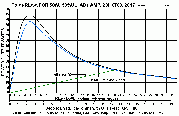
The upper curve is for anode output Po including all winding
losses.
The lower curve is Secondary output Po to nominal Sec RL.
---------------------------------------------------------------------------------------
So what sort of OPT could be used ?
Fig 6. 60W 50% UL OPT for 6k4 : 1r8, 4r0, 7r2, 16r0.
Includes links for CFB.
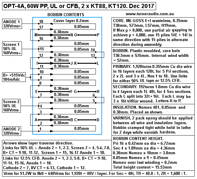
This is slightly better than the other UL OPTs I wound for 5050
amps I sold.
Details show Pri taps for 50% UL. For slightly more maximum AB
Po for RLa-a less than 7k0,
use 37.5% UL with Screen 1 to 13-14, and Screen 2 to 5-6.
I have allowed for use for 12.5% CFB where Pri layers 6 to 7 and
12 to 13 are devoted to cathode.
Insulation each side of these two layers = 0.38mm Nomex to
ensure arcing would be impossible.
Properties of OPT-4A :-
Weight 6.5Kg, Plan size, lams horizontal, 115mm x 96mm, Core
stack H = 74mm, height oa
windings = 120mm.
Min Lp > 60H at minimum µ approx 3,000.
LL referred to Pri < 5mH. Ca-a < 800pF.
Bandwidth at 55W 6k4 : 4r0, 50% UL, 18Hz ( Fsat ) to 65kHz with
NFB.
RwP, 1,920t x 280mm av TL x 0.355 Cu dia wire = 97r.
RwS, 4 // 48t x av TL 280mm x 1.0mm dia wire = 0.0764r.
RWS at Pri = 122r. Total Rw at Pri input = 219r. Loss % with
RLa-a 6k4 = 3.3% in class A,
about 4.7% in class AB.
For Va-a = 640Vrms, Bac max = 1.5T, Fsat = 22.6 x 640V x 10,000
/ ( 38mm x 72mm x 1,920t x 1.5T )
= 18.4Hz.
OPT-4A has Primary windings 6-7 and 12-13 available for 12.5%
CFB instead of the 50% UL.
But for CFB, the same B+ for anodes is used but a separate
+350Vdc rail should be used for both
output tube screens.
The lower Eg2 makes Pdg2 less because Ig2dc is lower. But the
Eg2 +350Vdc can be easily shunt
regulated to make the output tubes quite immune to variations of
mains levels, and the shunt regulation
can be set up to make sure Eg2 can sag if Ig2 dc becomes
excessive.
Higher Vac must be applied to grid1 but probably the ECC99 will
handle all that OK.
UL is simplest, and you should know that I know there is more
than one way to make a really good
PP tube amp. My 8585 and 300W amps use CFB. But I have heard
great music with UL.
Table 1. Load matches available OPT-4A
RLa-a,
1,920t
|
Sec RL
6 // 32r
ZR 3,600
|
Sec RL
4 // 48t
ZR 1,600
|
Sec RL
6 // 64t
ZR 900
|
Sec RL
2 // 96r
ZR 400
|
Class AB
Po max
at Sec
|
Class A
Po max
at Sec
|
4k0
|
1.11r
|
2.50r
|
4.44r
|
10.00r
|
68W
|
4W
|
5k0
|
1.39r
|
3.13r
|
5.55r
|
12.52r
|
64W
|
5W
|
6k0
|
1.66r
|
3.75r
|
6.67r
|
15.00r
|
59W
|
6W
|
7k0
|
1.94r
|
4.38r
|
7.77r
|
17.50r
|
55W
|
7W
|
8k0
|
2.22r
|
5.00r
|
8.88r
|
20.00r
|
50W
|
8W
|
10k0
|
2.78r
|
6.25r
|
11.10r
|
25.00r
|
42W
|
11W
|
12k0
|
3.33r
|
7.50r |
13.33r
|
30.00r
|
35W
|
13W
|
14k0
|
3.88r
|
8.76r |
15.54r
|
35.00r
|
31W
|
15W
|
16k0
|
4.44r
|
10r0
|
17.76r
|
40.00r
|
27W
|
17W
|
20k0
|
5.56r
|
12.52r
|
22.21r
|
50.00r
|
----
|
22W
|
There is no point allowing RLa-a to be less than 4k0, because
THD and IMD go too high, and damping
factor too low. The use of 4 possible wasteless secondary
connections means that total winding losses
do not change. For example, If Pri RLa-a = 6k0, then total
winding losses = 3.5% for
Secs = 1.66r, 3.75r, 6.67r, 15.00r, and there is no change to F
response.
Maybe there's a load match for everyone.
Just when you thought I'd finished, have a look at this
:-
Fig 7. 60W PP class AB UL amp, ECC99 driver, KT120.
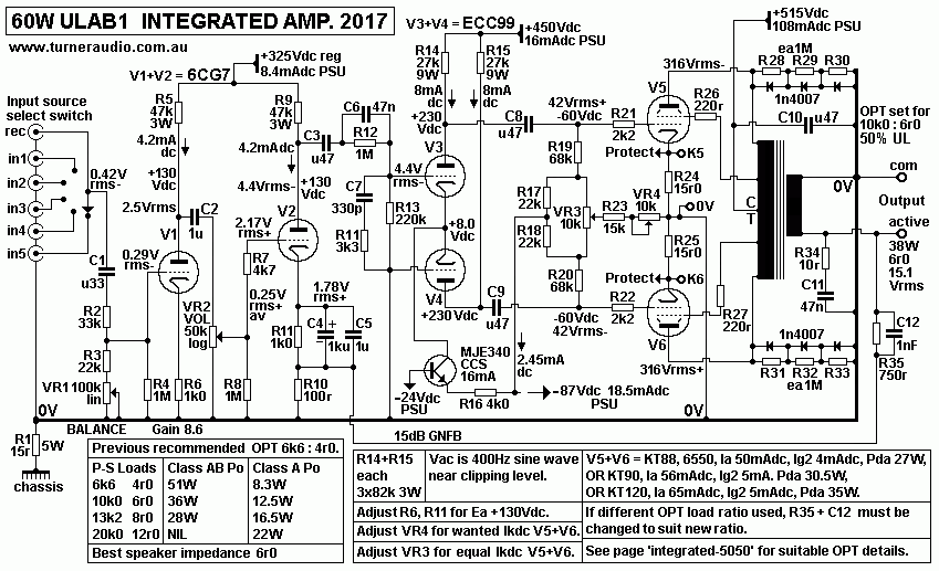
Fig 7 shows a natural progression to KT120, which were not
available in 2000 for 5050.
The driver stage uses ECC99, a mini 9 pin twin triode where each
triode works about as
well as EL84 in triode mode.
So why use KT120?
Let me compare KT120 to KT88, used in above amp with approx Ea =
+500Vdc.
For all class AB amps idle Pda < 0.6 x Max rated Pda.
KT88 ( and 6550 ) Pda max = 42W, max idle Pda = 25W, Ia =
50mAdc. If RLa-a = 6k4,
initial class A Po = 8W.
KT120, Pda max = 60W ( ? ), max idle Pda = 36W, Ia = 72mAdc. If
RLa-a = 6k4,
initial class A Po = 17.6W.
But KT120 heater power is 2W more that KT88, and if you get 16W
class A, its quite enough
and Iadc should not exceed 70mAdc. Nobody has compared the
temperatures of these tubes
when set up together to really see just how well KT120 can
handle the higher Pda. I don't mind
recommending Ia not exceed 65mAdc for for Pda = 32.5W.
Characteristics of KT88 and 6550 and KT120 are all about the
same for high RLa-a values
used for hi-fi amps.
Do not ask me which tube sounds the best. If anyone wants to
make a pure class A amp,
I suggest lower Ea = +400Vdc, and Iadc could be then 90mAdc, and
each tube sees RLa = 4k0,
RLa-a = 8k0 and you get 32W pure class A.
But then I have to ask, would 4 x EL34 be better? they would be
cheaper. Ea = +400Vdc,
Ia = 50mAdc, each has RLa = 7k2, and for the PP quad, RLa-a =
7k2, and class A Po = 36W.
KT120 certainly is a fashionable tube to use, and its
reliability should be excellent and just as
good as NOS tubes originally made in UK or USA, because that's
been my experience.
The above Fig 7 includes VR3 for equalizing Ikdc for V5+V6, and
VR4 to adjust overall Ikdc for
both output tubes, and for 3 chassis sockets for 2mm DMM probes
to measure Vdc across
R24+R25, both 15r0. Where wanted Ikdc is higher than 52mAdc for
KT90, KT120, the protection
schematic must be changed to allow for higher +0.975Vdc across
15r0 for Ikdc = 65mAdc.
Fig 8. Power transformer details for 5050 ( or 9090 ) 2
channel amp.
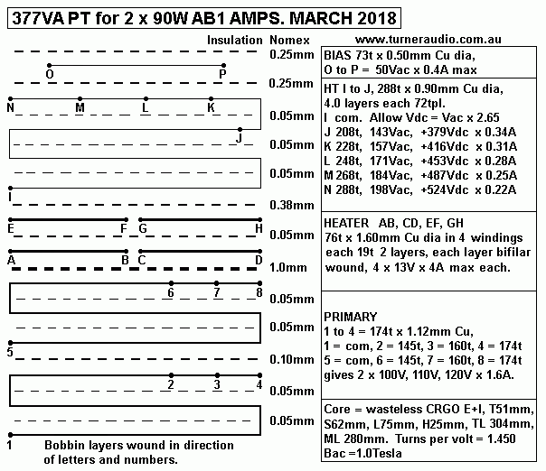
There are more notes about this PT in powertranschokes.html
Fig 9. This is earlier PSU similar to what I used in 2000
for original 5050.
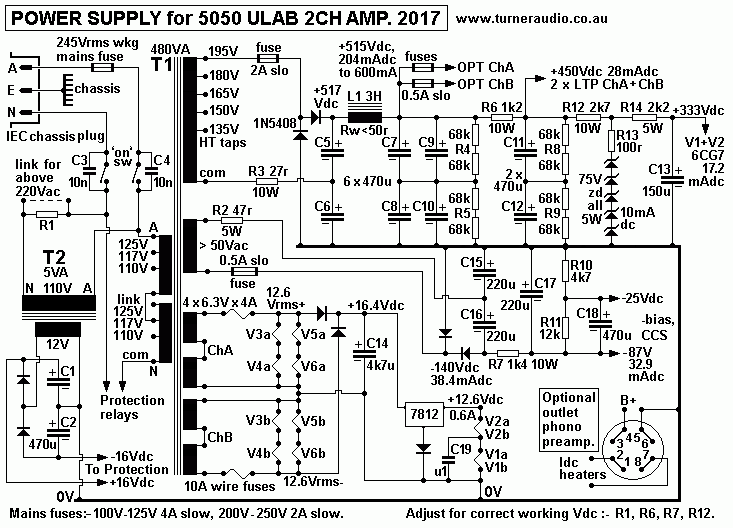
Please use the 2018 version of PSU in Fig 4 above, and you'll be
so glad you did.
Back to power amp directory
Back to Index Page


