DYNACO
ST70 RE-ENGINEERING.
This page contains :-
General talk about what I did to an ST70 in 1999.
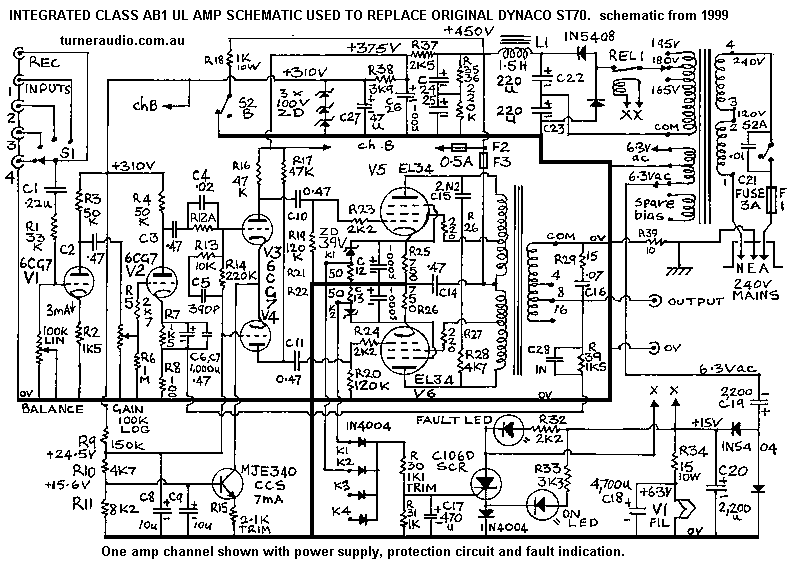
Fig 1. Very untidy and hard to read schematic for my 1999 work on
ST70.
The work included adding inbuilt line preamp, source switch, dual
gang volume pot, balance pot,
and numerous good quality RCA input terminals and new speaker
terminals.
Fig 2. MUCH BETTER schematic for one channel of reformed ST70 amp,
with cathode bias,
no need for any negative supply. Many notes.
Fig 3. Active protection schematic for any amp with multiple
output tubes and cathode bias.
Fig 4. Schematic for PSU for Reformed ST70 using original 1960 PT
if it is found to not run hot.
Notes about why, etc.
Fig 5. Schematic for generic 35Watt PP UL amp which does use a
negative supply for CCS
in LTP stage. Can easily be altered for fixed bias.
This page was first established in about 2006, and the latest page
upgrade has been in
May 2014, when I also created a page about the Dynaco MkIV monoblocs
which have
a very similar schematic to one channel of the two channel Dynaco
ST70.
My apologies to all for presenting a very messy Fig 1 which is a
hand-drawn schematic for
what I did to an ST70 in 1999.
Before 1999, I bought an ST70 which was offered to me for $200 and
which was in appalling
condition after being parked in a garage for 15 years after a
couple of output tubes had died.
There were lots of problems within the amp. I didn't like the
typical Dynaco schematic
with 7199 / 6AN8. I thought the power supply could be a lot better
and the driver amp could
be improved so I decided to strip the whole amp and start all over
again. The PSU had a
117Vac mains input which ran way too hot with a correct step down
tranny for 240Vac Oz mains.
I re-wound the PT for use with our Oz mains of 250Vac most days,
using more turns per volt
and a stack of iron 25mm higher than original. The PT ran much
cooler and quieter.
I used Si diodes in revised PSU with higher C values and I
retained the tiny filter choke
which is actually about only 1H with Idc present.
Unfortunately, I didn't photograph it before I sold it easily when
I placed it in a local hi-fi store for
sale on consignment. Its top cover looked better painted black. It
ran cool because I drilled
8mm holes all around each output tube socket and I fitted 15mm
feet under the amp and
perforated steel bottom cover to allow generous air flow up
through bottom and up
around tubes.
Fig 1 schematic below was created before I had become able to use
Windows MS Paint.
I also had very little time to spare. Fig 1 is extremely cluttered
and unclear since it includes
power supply for both channels and one amp channel plus its
protection circuits.
Notice the reformed ST70 has line level preamps added to both
channels and was integrated
so a separate integrated preamp was not needed with most modern
input signals from CD players.
Needless to say, the circuitry under the chassis was crowded, but
I found enough room for everything.
The 1999 modification needs complete re-appraisal.
I have since learnt to create schematics in MS Paint, slow and
laborious, but better looking, and much
for anyone else to follow. I often use 2 or 3 sheets to contain
all the info on audio amp, PSU and
active protection measures.
Fig 1. Hand drawn ST70 schematic 1999.
Rather than explain what I did in 1999, I now present a reformed
ST70 schematic drawn May 2014
which includes better techniques than in 1999.
Fig 2. Properly drawn ST70 amp, 1 channel.
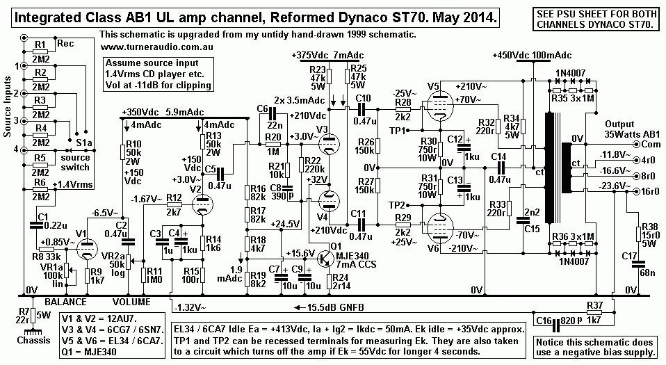
Fig 2 shows one channel of the ST70 amp with slightly more
optimized values and a change to
cathode biasing of EL34.
The original Dynaco printed circuit board for two 7199 / 6AN8
triode-pentode input/driver tubes was
removed to the rubbish bin.
I replaced the whole board with a small brass plate and with 4
ninepin sockets to allow the use of two
12AU7 for preamps and power amp inputs - and two 6CG7 for Long
Tail Pair differential balanced
voltage amps. There is nothing wrong with using only 6CG7 as shown
in 1999 schematic, but now
I think using 2AU7 for the line preamp and the power amp SET input
gain tube is better because
12AU7 has less voltage gain, and huge gain is not needed. The two
12AU7 can each have their
12.6V heaters between pins 4&5 both strapped across 12.6Vdc
heater supply. See the reformed
PSU further down this page. In fact, 12AU7 or 12BH7 may be used
for LTP. Preamps can be 12AU7
with power amps inputs 6DJ8. But whatever is done, some changes to
R&C shown will have to be
very carefully calculated and implemented.
V1 is 1/2 12AU7 for line stage pre-amp with gain = 15dB with
unbypassed R9. With balance control
included there is a 3dB loss of input signal with R8 and VR1. So
overall preamp gain = 4.6 x, or +13.2dB.
This assumes a CD player input = 1.4Vac, and you get V1 Va =
6.5Vac, and VR1 volume control
then reduces this to whatever is needed for listening. Volume is
set at -11dB or say about 2pm for clipping,
and at about 9am for normal listening. An old FM tuner with
standard 0.2vrms output will need volume raised
to maybe 2pm for normal listening, but such input will not be able
to make the amp clip, and nobody
needs to make the amp clip.
V2 is power amp input SE triode with GNFB applied to its cathode
R15. V3 & V4 form LTP with differential
gain approx 17x.
Q1 is a CCS for commoned cathodes which ensure the two Va have
equal amplitude if the anode loads
are equal with modern metal film anode load resistors. Notice that
I have the Q1 set up running with positive
base and emitter voltage supplies. This means Ek of V3, V4 are at
+32Vdc, and the B+ for the two triodes is
+375Vdc - 32Vdc = 343Vdc, and their Ea = 178Vdc. The Ea and Ia is
high enough to obtain very low
THD at 25Vrms output with 47k dc load and following 150k bias
resistors which give total triode load of 36k.
V5 & V6 output EL34 work in a normal cathode biased EL34 class
AB1 ultralinear output stage, with
UL taps at 33%. Each EL34 idles at Pda = 20Watts. This means the
maximum possible pure class
A = 18Watts, requiring the RLa-a = 14k4. The OPT has nominal ZR
4k3 : 4, 8, 16, so to get pure
class A you will need to connect speakers with Z = 13r2, 26r4,
52r6. The only practical way to get pure
class A is to use 16 ohm speakers connected to the 4r0 outlet.
If anyone wanted to increase the possible class A, and get more
class A with a lower Z speaker,
they can have EL34 idling at 25Watts each and use a lower B+ of
say +425V with Iadc = 60mA,
and then 22 Watts class A is possible with RLa-a = 12k5, but you
still need an 11r4 speaker at 4r0 outlet.
It is quite impossible to all pure class A Po with 4 or 8 ohms
with EL34, and use of KT88
with higher Pda at say 32 Watts each and Ia at 80mA is needed to
get RLa-a to 9k0, which allows use of
8r0 speaker at 4r0 tap. Class A Po max is 28Watts each with the
high Ia in KT88. Original ST70 power
transformers would probably overheat badly if supplying 320mAdc to
a quad of KT88, so I do NOT
recommend using KT88 unless you keep the Iadc at the same idle
50mAdc used in EL34.
Using an 8r0 speaker connected to 4r0 outlet will raise the RLa-a
to 8k6. If Ia in each EL34 = 45mA, then the
class A possible = 8.7Watts, and class AB total up to about
25Watts. This should sound better than with 8r0
speaker connected to 8r0 outlet where you will get 4.3Watts of
class A and 35Watts AB total.
I did not think I needed to retain fixed bias because cathode bias
gives the best natural regulation of Ek at idle.
The 35Watts Class AB1 possible in original ST70 relied on fixed
bias, where Ek remains near 0Vdc.
But with GZ34 the B+ of +450Vdc sags considerably if you crank
volume to 35Watts.
I have used cathode bias, and with Si diodes and a better PT with
lower winding losses so B+ does not
sag much. But Ek with cathode bias can rise from my idle value of
+35Vdc to maybe +60Vdc if the RL
is low and amp is brought up to clipping with a continuous sine
wave. But average levels of music signals
are NEVER the same as a sine wave. Average music levels are
governed by the onset of clipping at
the peaks in the music signal, so during drum beats and other
short lived transients. The use of large value
cathode bias caps, say 470uF means that Ek stays virtually
constant while producing an average level of
say 5Watts, with peaks rising to 35Watts. So if a Vdc volt meter
is clipped across the Ck, you will be surprised to
find the Vdc won't change while the music is intolerably loud.
In Fig1, 1999, I used 5 Watt 39V zener diodes in series with 47r
5W across the Rk & Ck network.
This worked to limit the rise in Ek to about +44Vdc for Ia total
of 144mAdc, possible during sustained
class AB working with a sine wave, with most Iadc flow through
zener diode and 47r. The rise of Ek
was not enough to mis-bias the tube, and THD remained low, and Po
high, all very like fixed bias.
At low Ia, the zener diodes do not conduct at all and the 750r are
free to act to keep the Iadc regulated.
In practice, the zener diodes rarely will ever conduct because Ek
will remain fairly stable with normal
average music levels even where peaks of signal reach clipping.
Therefore there is not much need of the zener diodes or 47r, and I
never used the method in other
class AB re-engineered and new hi-fi amplifiers after 1999.
In the 1999 schematic, the zener diodes + 47r will allow about
+4Vdc across 47r before the protection
circuit activates to turn off the amp. If a tube becomes faulty
its Iadc could rise to 144mA before the
amp is turned off. This means the tube could be destroyed by
overheating if the idle Ikdc rose to
just under 144mA. THEREFORE, the resistances between 47r and SCR
gate would need very careful
adjustment so that Vdc across 47r was maybe only +2Vdc, when total
Ikdc = 98mA. But that all means
that Ek would not have to rise very far before tripping the the
SCR.
Fig 1 just acts like having a 144mA fuse in the cathode circuit -
it stops catastrophic melt downs.
Two years after the new owner bought the amp he brought it to me
because the protection circuit kept
tripping. One EL34 had developed a dry joint inside one heater
pin. So only one EL34 of a pair in one channel
was turned on. When music was played, the Idc in this EL34
saturated the E&I OPT core and large signal
currents with high distortion flowed at low levels, and amp was
turned off BEFORE the tube could get hot.
I re-soldered the heater pin in EL34 and the amp returned to
working perfectly and I have not seen it since.
In my revised Fig 2 amp schematic, and without the zener diode +
R, Ek is allowed to rise to +55Vdc
without any signal before the amp is turned off, when Ikdc = 73mA,
and Pda = 30Watts. If the EL34 has
Ikdc at say 70mA, its Pda = 29W, and will be slightly hot, but
will survive being ignored for awhile, and
when Ikdc goes just a bit higher the amp is turned off. This is
more user friendly than if I stayed with zener
diodes a low value shunt R.
There are a number of other reasons why excessive Ikdc flow may
occur, and why it is good practice
to have such protection, such as :- turning up the volume with a
shorted speaker cable, or a random
failure of an EL34 occurs, might be old age, or teenagers are in
charge of volume control.
The Dynaco company claimed their amps were stable, but I found
stability to be conditional.
Nearly all amp makers said their amplifiers were very stable, but
failed to say it only applied if a pure
resistance load was used. In other words, the stability depended
on a "correct" load which was the
ideal speaker which resembled a pure resistance of a single
nominal value. So the amps they made
were NOT unconditionally stable, and many oscillated at LF without
a speaker connected, or at HF
and almost always if a 0.22uF cap was across the output with no
speaker load. Most amp makers
avoided the extra work of making their products unable to
oscillate without any load or with at any
possible combination of L, C or R load, Most amp buyers do
not understand stability. They think,
OK, its on the bench, it won't fall off, so its stable, OK? WTF is
oscillation? What is the load?
what is inductance, capacitance, resistance and phase shift? 95%
of amp buyers are so ignorant
they don't ask such questions. I'm not here to explain and teach
basics which keener minds pursue.
All amps must be made stable, and free of any oscillations under
any condition whatsoever.
Peaks in the sine wave response between 0.0Hz and 30Hz and above
20kHz to 2MHz should be less
than +1dB with resistance loads, and not above +6dB with pure C
load anywhere above 20kHz.
Overshoots on square waves should not be greater than 6dB. The
likelihood of LF oscillation is
most likely with no resistance load at output, and at HF when a
sole capacitor load of 0.05uF to
1uF is used. Oscillation is caused by phase shift reaching 180
degrees between input and output,
and when Global GNFB is used, the NFB network sends what has
become positive feedback, GPFB,
back to input which allows oscillations. The cause of phase shift
are R&C coupling, Miller C,
leakage inductance, primary inductance, multiple stages in the
amp, and the amount of NFB used.
This amp uses several R&C networks for stability.......
HF :-
C8 & R21 are a "Zobel" network to reduce HF open loop gain
above 20kHz, and lessen open loop phase
shift between 40kHz and 300kHz, thus keeping NFB negative, not
positive.
C15 & R34, across OPT primary. This network lessens output
tube gain above 20kHz and provides
a resistance load when most speaker Z has risen due to their
inductance in voice coils. The resonances
due to LL and shunt C become damped by the R36 and ringing on
square waves is lessened.
Use of a pair of zobel networks, say 2k2 + 4n7 may be tried from
OPT CT to each anode connection.
R38 & C17 across 16 ohm winding. This loads the OPT sec with a
resistance at above 150kHz.
It may not seem important, but I had a reason to add this network.
Some amps have 15r0 + say 0.22uF and XC = R at 48kHz, so at
100kHz, the network is mainly resistive.
R37 & C16 in GNFB path. R37 sets the amount of NFB, and the
value of ß, the fraction of output signal
appearing at top of R15, 100r, and hence applied to V2 cathode, so
that the tube acts like a differential
amplifier with two inputs, to grid, and to cathode.
C16 causes some phase advancement of NFB signal which compensates
for phase lag in tubes and from
LL of OPT. C16 must NOT be too large or else very high F
oscillations can occur. C16 is interactive with
C8 used at V2 output.
LF :-
C6 & R20 are parallel R&C to reduce LF open loop gain
below 32Hz so that at 3.2Hz,
the input to V3 is attenuated by about -14dB, and effective GNFB
at such LF is
reduced by -14dB, and the amp has its "margin of stability"
extending down to F where
there is very little gain at all.
The values for all C and R used for stabilizing are a guide only,
and must be confirmed by
experiment to be best.
Nobody should assume values I show in this schematic will always
suit the amp they build
or modify.
Fig 3. Active protection.
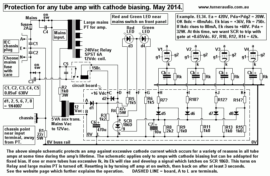
Fig 3 shows the protection schematic I would use now. The circuit
board shown may usually
be less than 40mm x 120mm, and able to be fitted somewhere under
the chassis. There will be
flexible lead wires from points A to L to various other circuit
components and connections.
I show points H, I, J, K taken to cathodes of 4 output tube
cathodes where cathode bias is used.
Then I have R7, R10, R12, R14 shown as unknown R values. But all
four R have the same R,
and just what would it be?
When applying this schematic in the reformed ST70 with EL34, we
must know all we are doing, so,
we know from Fig 2 that Ikdc = about 47mAdc, and Ek is about
+35Vdc, when Pda is a very safe
20Watts. We want the protection circuit to work when Ek reaches
+55Vdc when Pda = 30Watts.
The SCR will latch on when its gate voltage reaches +0.65Vdc, or
just over. The gate input current
for "sensitive gate" type of C106D is 30uA, and can be neglected.
The 0.65Vdc is across R8 2k2
So we need 0.3mAdc input to gate circuit at +0.65Vdc. The diodes
d5 to d8 begin conduction
when forward voltage = about 0.45V, and expect 0.5V at 0.3mA for
1N4007. Therefore the Vdc
across any one of R9, R11, R13, R15 1k0 much be +1.15Vdc before
the SCR "trips".
Suppose V1 has excessive Ek at +55Vdc.
The current in diode d5 plus in R8 1k0 = 0.3mA + 1.15mA = 1.45mAdc
for SCR to trip.
This total must flow in R7, and Vdc across R7 = 55V - 1.45V =
53.55V so the R7 must be calculated
as V / I = 53.55V / 1.45mA = 36.9k, and a non standard value. Fig
3 shows I have calculated 42k,
but R7can probably be 39k. The higher the value of R7, the higher
is the Ek and Iadc, so less
protection.
The lower the value of R7, the lower is the Ek and Ia, so
protection is more sensitive,for SCR to trip.
The operation MUST be carefully tested by increasing grid bias
positively with a pot, and slowly,
and measuring the Ek when SCR trips. The other test is to use a
dummy 2 ohms at 4r0 outlet, and
slowly crank up volume to clipping, and the Ek rise should trip
SCR at just over clipping. This test
also means that 4r0 or 8r0 used at 8r0 and 16r0 outlets also cause
SCR tripping at clipping.
Use of 4r0 loads connected to 16r0 outlet is a very bad mistake
often made by many owners who
don't realize there are any laws of Physics. My protection circuit
will annoy them and they'll never
understand I am trying to save them from the effects of their
ignorance.
Fig 4. Reformed ST70 PSU.
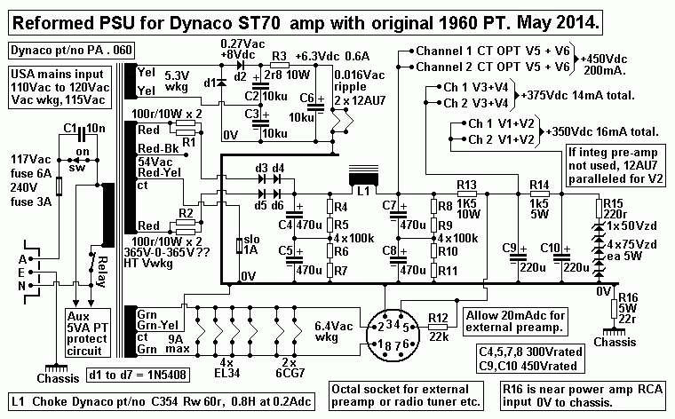
Fig 4 shows a slightly better PSU than I used in 1999. I used what
I could scrounge from local
cheap suppliers. Now the prices for electrolytic caps are cheaper
in real terms and very reliable,
thanks to modern computer controlled production.
The Fig 1999 schematic shows deletion of GZ34, and use of a PT I
wound myself and a voltage
doubler B+ supply. I used slightly bigger uF value for filter
capacitors which were placed in a
metal box on the chassis top and in the area available after
removal of old caps and tube rectifier.
Fig 4 above shows what could be done if the original PT is
retained. This assumes your existing
PT runs nice and cool, T rise < 10C above ambient. The sample I
rebuilt in 1999 had a very hot
PT after a couple of hours.
Using replacement PT for ST70 is not difficult if the PT used has
same plan dimension and has
higher stack which can give the same required voltages with higher
current ratings.
then the use of KT88 / 6550 / KT90 can be considered. But if an
external stereo line preamp plus
phono stages is to be powered from the existing octal socket, then
6.3Vac heater current may
total 8A. So the 6.3V winding should be well rated for 9A.
On a new PT, there is no need for a 5Vac winding. The new PT
should be able to provide DC
heating for all tubes except the output tubes, and including any
tubes in a remote preamp or
radio tuner etc. Any new PT should have a spare pair of 6.3Vac
windings each rated for 3A,
and usually you can make two supplies of 12.6Vdc or 6.3Vdc, with
one supply for power
amp chassis tubes and other for remote preamp or tuners etc.
In Fig 4 I show 2 x 6CG7 heaters with same 6.3Vac used for EL34.
These 6CG7 are the two
long tail pairs in power amps. The two 12AU7 used for possible V1
integrated line amp
and power amp input V2 should have Idc heating which one often
finds is the best way to
keep the amp hum level very low.
If the integrated preamp is not to be included, V1 and V2 can be
paralleled with 1 x 12AU7
used for each channel where I show V2. The anode dc loads can be
reduced along with
cathode Rk so that Ia for both triodes totals about 7mA, with Ea
the same.
There are no pictures of the Turnerized Dynaco ST70 which was sold
before there was
a Turner Audio website.
The appearance was relatively unchanged except for absent tube
rectifier, capacitor
box on top of the chassis, increased size of power transformer, 12
x 8mm dia holes
drilled through steel chassis top around each output tube socket,
holes drilled in the
bottom cover, brass sub-chassis for more input tubes, selector
switch, balance and
gain controls on the front, led indicators, and a black painted
original cage over the amp.
The new owner said he liked to be able to hear the musicians
turning their pages,
and he liked the clear, warm, dynamic and untiring sound.
And here's another possibility......
Fig 5. Generic 35W UL amp.
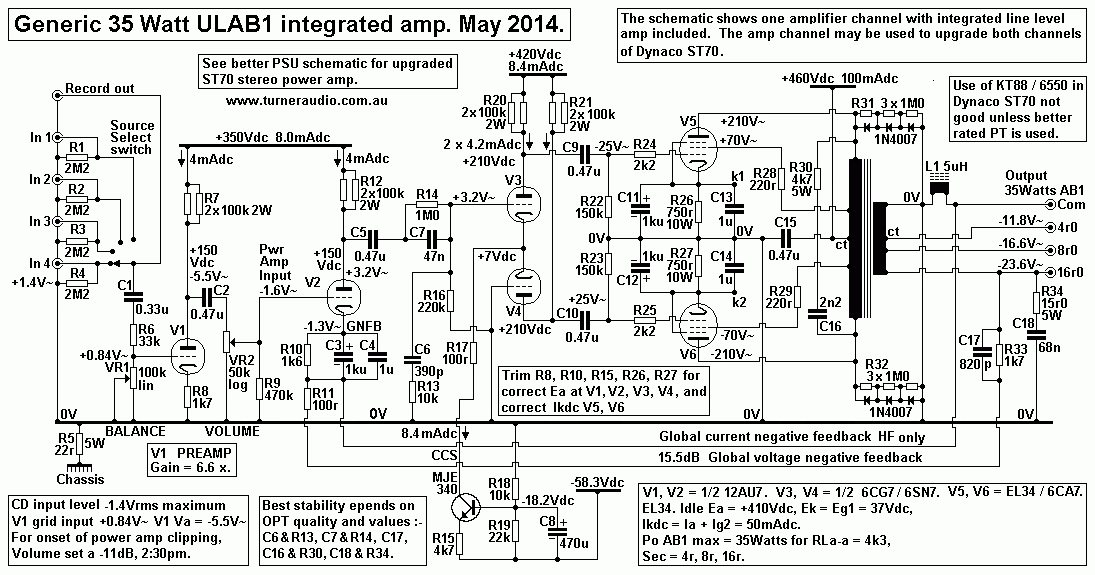
This amp channel shows very similar operation to ST70, but uses a
negative bias supply for CCS to V3, V4
cathodes to maximize the Ea of the two triodes and increase Ia,
and lower the LTP distortion.
My other closely related page is for Dynaco MkIV monobloc
re-engineering.
To Dynaco MkIV monobloc
re-engineering
To Re-engineered amps
<
To Index Page 


