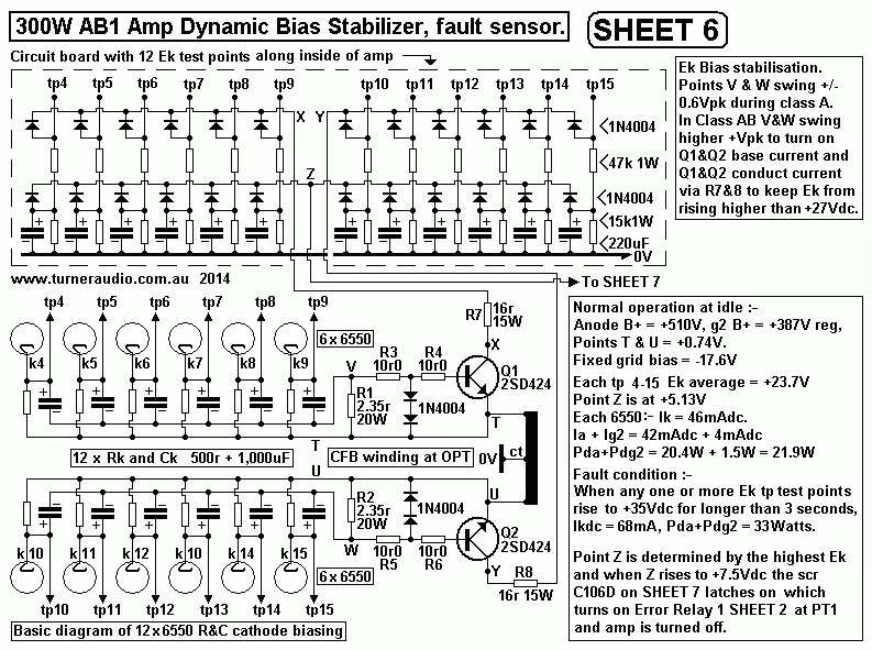
SHEET 6, bias failure detection.

Sheet 6 can be read in conjunction with Fig
5 at my page on bias stabilization.
Sheet 6 includes the circuit method for detection of excessive
Idc in any one
or more 6550 in the 300Watt amp.
The dc operation of the tubes in any tube
amp is very important for good
music and active protection is needed to prevent mental
anguish with large
repair bills.
The dc operation should be considered a separate operational
to the ac
or signal operation.
DC operation and twelve Ek bias test
points.
The top left part of Sheet 6 shows 12 test points and 12
R&C networks
each with with 47k, 15k, and 220uF, and all this is mounted on
a board
400mm x 50mm mounted inside a long side of the chassis. Test
points
4 to 15 are accessible via 12 x 6mm holes in chassis side.
Checking bias is OK?
This is done with NO signal present and a minute or more after
amp has
been turned on.
An amp owner can use a $10 digital multimeter to measure Vdc
at each
test point. The meter should be set to 200Vdc range and red
probe
held onto test point without also touching chassis, and black
probe to
a nearby chassis screw. Each
Ek should be between +22dc and +26Vdc.
An owner can see if all tubes are conducting dc current, and
if any are
too little or too much. The +22Vdc to +26Vdc is what I measure
with 12
EH6550 made in about 2001, and which have had less than
500hours of use.
I assume replacement 6550 made in 2014 would measure
similarly.
The forward voltage drop across diodes
is about 0.55Vdc so expect point Z
Vdc = +5.15Vdc. The real Z Vdc is determined by the one 6550
which has
the highest Ek. The point Z drives a high impedance base input
of an emitter
on SHEET 7 which shows the active protection circuit.
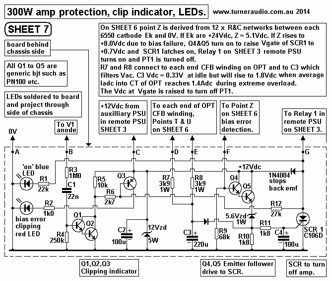
SHEET 7. Bias fault SCR and
Clipping indicator.

Normal idle emitter Vdc = +3.9Vdc. The
zener voltage = 5.6V, so no current
can flow and SCR gate is at 0V. The scr gate must rise to
+0.68Vdc to switch on
so point Z must rise to +7.6Vdc. There will be 0.111mA in R7
68k, and one of
15k will have 8.2Vdc, so 0.546mAdc so 47k must have 0.657mAdc,
so Ek
must be +39Vdc, with Ikdc = 76mAdc, or nearly twice the idle
current.
If more than one 6550 conduct too much
Idc then many Ek might rise so the
threshold Vdc where SCR1 is turned on slightly reduces which
is favourable.
Protection by turning amp off
internally.
When the SCR1 turns on, it turns on the Relay 1 in Sheet 3 PSU
which opens
the Neutral line to OPT1 primary, so the amp remains turned
off, yet with
mains switch still turned on. Owners must fix the problem lest
it keep
happening. But the amp is reset by turning off mains switch
and the +12Vdc
Protection rail quickly reduces and SCR1 turns off. When mains
switch is turned
back on in say 3 seconds or longer, the amp Vdc rails all are
re-established.
LED indication.
The SCR1 also controls the red and blue LEDs on power amp
chassis.
The blue LED draws little current through Relay 1 and to 0V,
and when blue
is lit it indicates all is well. When SCR1 conducts, the blue
LED is turned off.
The red LED is turned on, indicating a fault, and stays lit
until SCR1 stops
conducting during amp re-setting.
Clipping indication.
On Sheet 7 there are Q1&2 Darlington pair bjts which are
turned on by a
positive going peak signal of more than +1.2Vpk. This very low
current signal
is derived from V1 anode via R1, C3, R4. When the amp clips,
the sine wave Va
at V1 anode develop voltage peaks which exceed the maximum Va
when no
clipping occurs. The large sudden rise in Va is divided down
R1 and R3, Vdc
excluded, and Q1&2 will flash on and off with signal peaks
at clipping.
When Q1&2 turn on, Vc is pulled negative to turn on Q3
which turns the red LED
This action does not affect the SCR1 operation. So the red LED
can flash
at clipping, and also display when the SR1 is turned off, when
there cannot
be any clipping because whole amp is turned off.
While ever the bjts turn on, they bypass
collector current through R7 & R8,
16r, so that any rise in Ek due to rectifier effects of high
peak cathode current
limits Ek to no more than +3Vdc more than idle Ek, and this
rise is not enough
to turn on the SCR1.
There is square wave signal less than
+/- 0.8Vpeak across each of R1, R2
when the amp makes high class AB Po. The increase of overall
THD due to signal
at R1 & R2 is difficult to measure. During class A the Q1
and Q2 are dormant,
and have no effect whatever.
The arrangement allows the steady Idc bias condition to be
monitored without
having Ikdc flow in R1 and R2 which might stop Ek rising which
would prevent
protection circuit from working.
If an owner leaves his amp to make a
phone call, and a fault turns the
amp off, when he returns he will find blue LED on amp is off,
red is on
and at PSU green is off and red is on, to tell him there is a
problem.
The amp will appear to be cool, nothing is damaged. This
condition could
continue for years if house mains remain on without
interruption. Amp will
try to reset itself but if the problem remains the amp will be
automatically
turned off again.
Obviously, sensible ppl always turn off their amps if they go
out, or do not
want to listen to music.
If the protection PSU rail does not come
up to +12Vdc after turn on,
blue and green will not light up. There is no protection. Amp
will still work
and dynamic bias stabilizer will work but only fuse protection
exists.
A fault in protection circuits should be found lest the amp
work without
any active protection. But simple low voltage solid state
circuits as I use
are far more reliable than any tube circuits.
Circuit board used for protection.
I only use boards in tube amps for protection circuits which
have small
R&C and a few solid state parts all running cool. The
board with 12 RC
filters and 12 test points was easily constructed on a 4mm
board with
hooked solid wires for tracks with R and C and other parts
surface
mounted and soldered between wire tracks. Hand made boards are
more rugged than most mass produced printed circuit boards
which can
develop cracks in delicate tracks.
If the amp keeps turning off soon after
warm up, it may be possible to
find out which 6550 is conducting too much Idc cathode current
by
quickly measuring Ek to see which one rises to a high enough
Vdc
to trip the protection circuit. An audio tech might disconnect
the wire
from point Z to SCR driver to give more time to observe Ek.