BASIC
TUBE OPERATION 5.
October 2016.
This is about Differential Amps or Long Tail Pair, aka LTP amps
using two tubes,
usually triodes, to amplify the difference between two input
Vac.
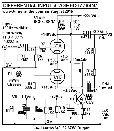
Fig 1, Fig 2, Fig 3 show schematics for LTP with 2 halves
of 6SN7.
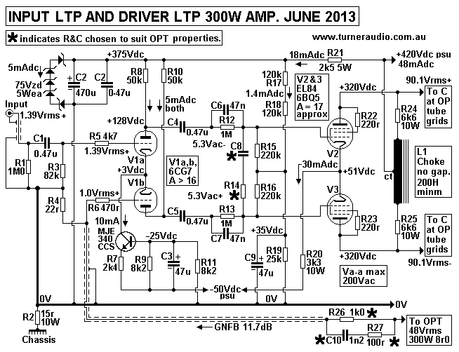
Fig 4 shows two cascaded LTP with 6CG7 and EL84 in
triode.
The LTP arrangement has rarely ever been used as an input stage
for any domestic
Hi-Fi because brand-name manufacturers were and still are
allergic to slightly higher
costs for the slightly added complexity.
But LTPs have been used in countless old fashioned scientific
amplifiers and for
balanced preamps. As seen in the Fig 1 schematic below, the amp
stage responds
mainly to the signal difference between applied input Vac. If
both input Vac have
the same amplitude and phase, almost no output can produced
because it is as
if both grids are connected together, and both triodes act as as
if in parallel, and
as an SE amp with high common cathode resistance so there is
little Ia change
and little Output at each anode. The ratio between the gain with
the two grids
having same Vac and gain for where there a difference between
grid Vac is
called the Common Mode Rejection Ratio.
Fig 1.

Fig 1 shows the two grid input signals may be a signal
from a CD player and
a global NFB signal from the output of a power amplifier.
To maximize the CMRR, the commoned cathodes of a pair of triodes
or pentodes
in an LTP are connected to a Constant Current Sink, CCS, Q1
MJE340, which
allows regulated and constant Idc to a -Vdc rail, and there is
extremely low Iac
change due to any Vac change at commoned cathodes of V1a+b.
The idea of constant current with Vac change is difficult
to understand
because we are used to always seeing Iac change with Vac change,
and R = V / I.
Ideally, the finite resistance of the CCS = infinite ohms, but
infinite R values are
rarely found in any amps. Resistance is usually considered a
positive quantity,
but can can rise to an infinite quantity, and then become a
NEGATIVE quantity
where there is a current reduction for an increase in Vac.
Negative resistances
are rarely ever employed in any amplifier, although in 1950s,
some tube amps
employed positive current feedback loops to reduce their
output resistance to
being negative, so that as output RL became lower, the amp Vo
output increased.
Alas, these amps quickly oscillated to death if the output
load was too low, or
shorted, and any use of positive FB anywhere was avoided
completely after
about 1960.
Q1 MJE340 has its emitter taken to a -45Vdc amp rail. Its
base is to centre of
R8 and R10 which produces about -23Vdc at base. R10 is bypassed
with C3 100uF
so that any Vac between 0V and -45V rail does not appear between
base and -45Vdc rail.
Without C3, 1/2 the PSU noise at -45Vdc rail will appear between
base and -45V
which will produce some Iac change at collector which has very
high resistance > 1M0.
But the cathodes are a low resistance load < 300r, so even
with some Iac change
produced by "CCS" the anode output will be negligible. C3 has Xc
= 159r at 10Hz,
and this bypasses the base input resistance < 10k, and the
paralleled R8 & R10, 4k1.
For the AF band, the Vac between base and -45V rail is so low it
impossible to
measure easily. The MJE340 with Idc = 10mA may have gm =
100mA/V.
Without R12 present, the collector resistance Rc would be
between 10k and 40k,
somewhat hard to determine. But we do not need to, and may
assume Rc = 20k
for calculations.
The effective Rc with emitter resistance Re = Rc + (
[ gm x Rc ] x Re )
= 20,000r + ( [ 0.1A/V x 20,000r ] x 2,200r ) = 20k + 4,400k =
4,420k
= 4.42M.
The calculation is similar to a 6CG7 triode with gm =
1.6mA/V, Ra = 12.5k.
If there is Rk = 2k2, Ra effective = 12,500r + ( [ 0.0016 x
12,500r ] x 2,200r )
= 12k5 + ( 20 x 2k2 ) = 56k5. The higher the gm, the
higher the effective Ra.
The MJE340 has gm about 62 times that of 1/2 a 6CG7, so it can
easily make
itself behave as a very high resistance which is estimated
to act like a 4.4M resistor
from cathodes to a -44,000Vdc rail. To preserve sanity, do
not use Vdc higher than
+500Vdc anywhere in your amps!
Slightly more complex arrangements with 2 bjts can give
collector resistance > 100M
= close to infinite. The stray capacitance between collector and
anything else and the
C4 shunting R10 will then determine the bandwidth of the CCS.
Extreme bandwidth
is not any advantage, and the MJE340 does a far better job than
use of a pentode to
provide a CCS.
Fig 1 LTP above uses 6CG7 or 6SN7, and Vac shown are
valid for both these
tubes when used as a good input stage with low THD and wide
enough bandwidth
in many PP amps. The THD of the Fig 1 LTP is probably less than
0.03% without
any GNFB. If anyone were to copy this schematic for an amp input
they may find
some differences in gain because the exact µ and Ra for samples
of 6CG7 or 6SN7
will be different. Other very suitable tube choices are 12AU7,
6DJ8, 12AT7, etc.
The Va from each triode will have equal amplitude within 1%
tolerance, and this
balance depends on the the use of a CCS at cathodes and on
having equal anode
loads for each side of the LTP. You could have a 12AU7 on one
side, and 12AT7 on
the other and both Va will remain equal, while there may be some
2H due to imperfect
cancellation of 2H because of the different tubes. The reason
why there is good
balance with CCS and equal anode loads is because the Iac change
in one tube
MUST be the same amount but opposite phase in the other tube;
the cathode
current remains unchanged.
The Vac shown also depend on the the finite resistance of
the Q1 MJE340 which
acts as an extremely high resistance current sink to commoned
cathodes of V1a + V1b.
I show a negative supply rail of -45Vdc but it could be -90Vdc
if this is derived from
a -Vdc bias circuit for grid bias of output tubes. Whatever -Vdc
rail is used, the Q1
base Vdc should remain at about -23Vdc, and the R12 increased in
value to get
10mAdc flow which sets the Iadc flow to both V1a + V1b.
The previous edition of this page from 2013 contained
several screen fulls of
calculations which almost nobody would have ever read fully
without falling asleep
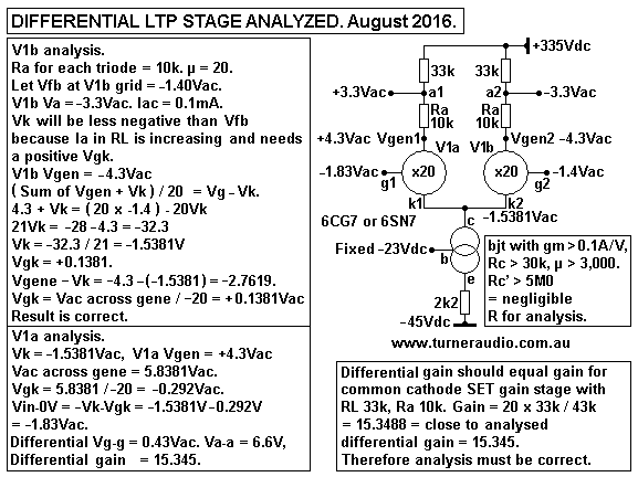
or going insane. I have another picture which shows the Fig 1
LTP reduced to a
Voltage Generator Model and all calculations are on the drawing
:-
Fig 2.

Fig 2 shows text for most explanations. The LTP has the
remarkable property
that the differential gain is the same as gain calculated for a
single 1/2 6CG7 in
common cathode for gain = 15.345. The LTP gain does not change
for a wide
range of Vac. And because the two triodes are balanced, their
THD is far lower
than for a single triode especially with a high Vac output.
--------------------------------------------------------------------------------------------------
DRIVER STAGE DIFFERENTIAL AMP.
My schematics for many PP amps between 25W and 300W show an SET
input
triode which may have MJE350 anode CCS Iadc source. This type of
SE input
stage minimizes THD to low forgivable levels by maximizing gain
by use of
RLa > 10 x Ra. The SE stages shown could be replaced with an
LTP.
Both will sound fine. All PP tube amps have a balanced driver
stage or an LTP
for driver which may be asked to provide up to 100Vrms to each
output tube grid
in some of my amps.
Some LTP samples also include a choke with CT used for anode
supply to LTP,
as seen at 8585 2006
and 300W
monobloc.
The 1947 Williamson amp used a balanced driver stage with
2 halves of 6SN7.
It did work well, but had a "short tail", ie, the common cathode
resistance was
1/2 the value of whatever Rk was needed to bias one triode of
6SN7 on its own.
These days, we would not hesitate to create a -100V rail and use
a higher value
for common Rk in a Williamson, and thus ensure there will be
better balance,
2H cancelling, and higher CMRR.
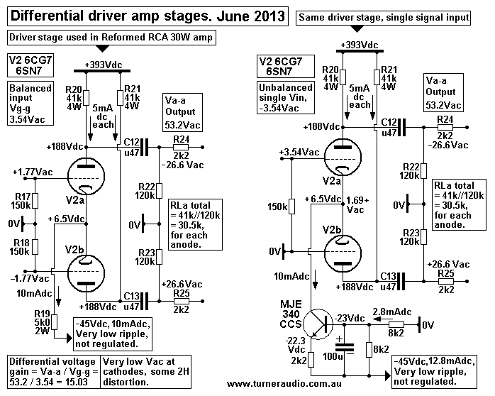
Fig 3. Here are two similar driver LTP stages.

These two LTP schematics are based on the driver stage
shown
at Reformed RCA 30W amp.
On the left side there is the exact stage used
for the RCA amp. The right side shows a single ended input to
LTP with one
grid taken to 0V, as in my 5050.
For these stages, I estimated the 6CG7 made by AWV in 1960s have
µ = 20, and
Ra = 10k1. The left LTP has common cathode current taken to a
-45Vdc supply
rail via 5k0. Because the there is a well balanced input to both
grids, each tube
operates with the same RLa total of 30.5k, from 41k//120k. The
Vac at commoned
cathodes is virtually zero except for some 2H. Each triode has
oppositely phased
Vac and Iac but the 2H current of both triodes has the same
phase, and therefore
appears at common cathodes as a local current NFB signal so
little 2H appears
at each Va.
The left schematic with R19 5k0 does not give very low
common mode gain,
and will be = approx 3.2. +0.1Vac at each Vg would produce
-0.32Vac at both
anodes. In practice, this does not matter because all PP output
stages with OPTs
have very good CMRR.
The differential gain with balanced Vg = Va-a / Vg-g = 53.2V /
3.54V = 15.0282.
The gain for each triode is same as a common cathode SET
where A = µ x RL / ( Ra + RL ) = 20 x 30.55k / ( 10.1k +
30.55k ) = 15.03, close enough.
But the left LTP does not give perfect Va balance if Vg are not
equal.
If V2b grid was to 0V and V2a grid driven with +3.54Vac, V2a Va
= -36.9Vac and
V2b Va = +26.6Vac. Vk = +1.6856Vac. V2b RLa has -0.8707mA,
and V2a RLa +1.2077mA, and the sum of these two Ia = cathode Iac
in R19 5k0
= 0.337mA. I calculated Vk = 1.6856Vac, giving the 0.377mA.
Vin must be +4.224Vac.
In other words, V2a has to make an equal but opposite Iac
to V2b Iac, PLUS make
whatever Iac change occurs in R19 5k0.
Differential gain = ( 36.9V+26.6V ) / 4.224V = 15.03, which
seems a coincidental,
but the imbalance ratio = ( 39.9 - 26.6 ) / 4.224 = 2.44.
Therefore we might expect that if a pair of Vg were +1.67V and
-1.87V,
a 0.2Vg-g difference of 11%, we would see 0.488V
difference in Va,
so expect -26.84Vac and +26.356Vac from the two anodes, a
difference of
less than 1%.
The use of R19 5k0 is not as good as a CCS, but is quite OK here
for a driver
in RCA amps where the input produces a very well balanced input
to V2a and
V2b above.
Although the MJE340 is not needed where drive to LTP is
balanced, feel free
use it. The output Va balance with well balanced Vg and without
the CCS was
found to be excellent because resistances used were matched
closer than +/-1%.
The right schematic with LTP with CCS at cathodes allows
the use of single
ended input to one grid with other grid to 0V, and the output
balance remains
perfect if the RLa are equal.
Output resistance at each LTP anode is a high ohm value
and poor when
considering each anode to 0V separately. This is a property of
all balanced amps
with commoned cathodes and high value cathode resistances or CCS
taken to a
negative or 0V rail. However, the loads on each triode including
capacitance of
next stage always remains equal providing there is no grid
current in output tubes
or cut off in LTP.
There is never any need to drive output tubes into grid
current where grid input
resistance reduces from say 2M0 to 1k5, with diode character. So
there is no need
for the Rout at each anode to be low to 0V because output
resistance between each
anode is quite good and = 2 x ( Ra // RLa ) = 2 x ( 10.1k //
30.55k ) = 15.18k.
This means that if Miller C between each output grid was a
rather high 100pF,
the F2 pole = 185kHz.
The LTP stage cannot easily produce drive voltages beyond
the onset of output
tube grid current region. Va clipping at each positive going
peak occurs at one
triode anode while the other triode anode produces a peaked
negative going Vac
which does not produce grid current and is entirely benign.
Gross overload produces
symmetrical clipping at the amp output, and recovery after gross
overload is instant.
For all operation up to clipping, there is low THD and IMD. The
LTP driver should
be designed to make twice the Vac needed for clipping. In this
example, expect
each Va to reach 62Vac at THD < 1% without output tubes
plugged in.
Where grid current drive of output tubes is required,
then there must be a
"buffer" stage used between the LTP and output tubes. In most
cases this consists
of an additional 6CG7 with its its grids driven by the above
gain stage and similar
C&R coupling, but cathodes are directly connected to output
grids, sometimes
with a series 1k0 to limit grid current. If output grid Eg =
-60Vdc, then the CF buffer
cathode resistance loads may been to be say 50k and taken to a
-310Vdc rail.
The CF grids will be at about -67Vdc, and they control the
output grid Eg2.
The CF driver anodes will need to be at least 220V above
cathodes at a fixed
+160Vdc rail. Unless CF drive is needed for class AB2 operation,
don't bother
ever using it ! Class AB2 use with beam tetrodes or pentodes was
once favoured
for high Po for PA amps where you could get a pair of 807 with
Ea +600V and fixed
Eg2 = 300V to make 80W if you drove the grids about +20V
positive. The distortion
was appalling, and for Hi-Fi, AB2 should not be used, so use
more output tubes
in AB1 if you want more Po.
But class A2 has been used for a number of commercially
successful amps.
The Ongaku 20W SET amp from Audio Note used a single 211 to get
rave
reviews in 1990s, and they cost $140,000, a truly absurd waste
of money,
IMHO. Ongaku used cathode follower drive to its 211. PP class A2
with a pair
of 211 would be very good with use of LTP with cathode
followers.
A pair of 6L6GC which make 15W in AB1 triode can be forced to
make 30W AB2.
Similarly, much higher triode Po is available with KT88 to KT120
with AB2. EL34
do NOT like AB2. But the AB2 operation is really never needed
when other methods
provide better overall performance with more reliability. But
where a large number
of parallel output tubes need to be driven and where the drive
Vac is high because
output tubes are in triode or where local output CFB operation
is used, then the
use of just one 6CG7 for a driver LTP is inadequate. Here is a
"blameless"
wonderful sounding input / driver combination for where a large
anode signal voltage
is needed to drive an output stage.
Fig 4.

The input LTP produces THD < 0.03% and output
THD < 0.1% at Vac shown.
The THD is mainly 3H, with 2H and other H at lower levels. At
listening levels the THD is
1/3 the above figures and much less than THD produced by an
output stage.
To Basic Tube 4
To Basic Tube 4a
To Basic Tube 3
To Basic Tube 2
To Basic Tube 1
To power amp directory
To index page


