SE OPT CALCULATIONS PAGE 1.
Last edit 2018.
FOR SINGLE ENDED AMPLIFIERS with OPT Idc flow in one direction only.

(A) RDH4, SE amp history, trends and preferences.

(B) Tables 1, 2, 3 for SE operation from some common power tubes.

(C) Biasing of grid g1.

(D) Calculate anode loads for maximum SE anode Po.

(E) Design OPT for 1 x EL34 pentode with or without CFB.
Graph 1. Po vs RLa, 1 x EL34.

(F) Ra curves for EL34 pentode and triode. Eg1 - 0V Eg2 +250V or +350V.
Fig 1. Ra curve for Eg1 = 0V with Eg2 = +350Vdc, or +250Vdc, also with triode Ra curve.
RLa loadline for 4,850r with EL34 idle Ea +400Vdc, Ia = 58mAdc

(G) Calculations for RLa, Po, etc, for SE Triodes, without load line analysis

(H) Loadline analysis for 5 loads for 1 x SE EL34 / 6CA7 with some simple calculations.
Fig 2. Five Loadlines for EL34 with CFB, Ea 350V, Ia 60mAdc.
How to draw loadlines Steps 1 to 12.

(I) DESIGN SE OPT-5A. For 12.6W, for 1 x EL34 or 6550.
Steps 1 to 16, includes Table 5, Wire sized Grade 2 winding wire.
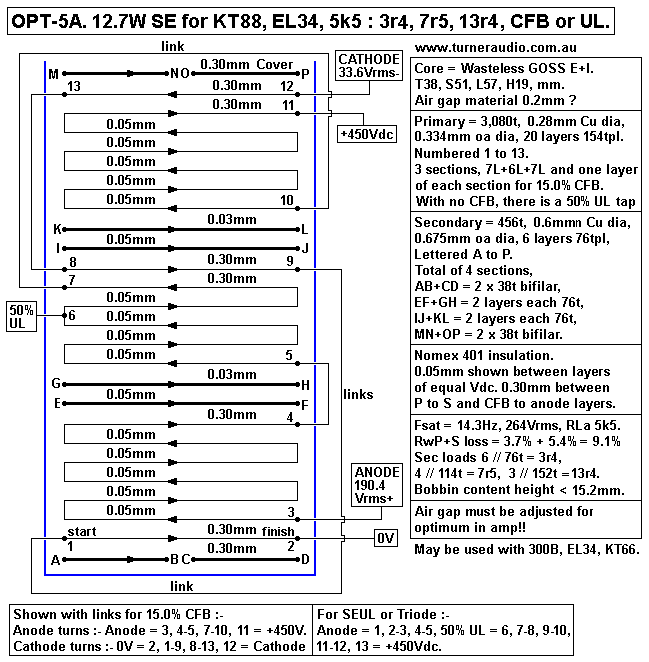
Fig 3, OPT-5A, 12.7W, RLa 5k5
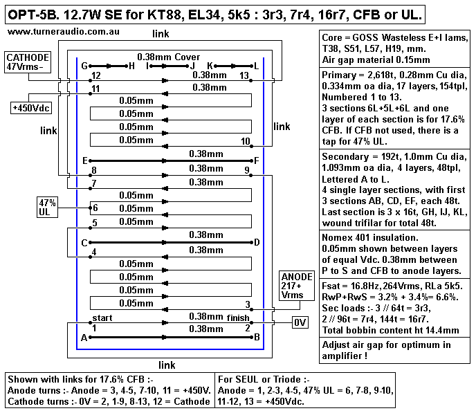
Fig 4, OPT-5B, 12.7W, RLa 5k5
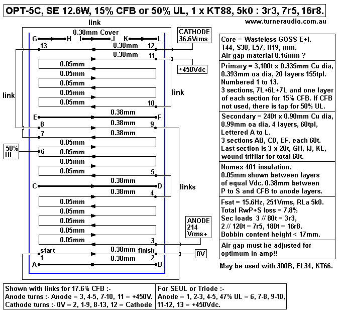
Fig 6, OPT-5C, 12.6W, RLa 5k0
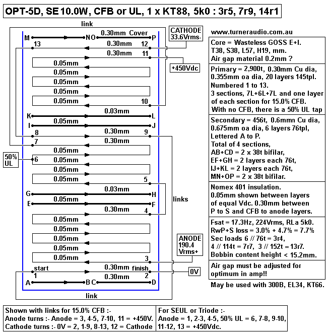
Fig 7, OPT-5D, 10W, RLa 5k0
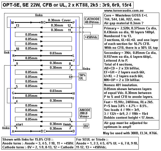
Fig 8, OPT-5E, 22W, RLa 2k5

Tables 6, 7, 8, 9, interleaving pattern possibilities for SE OPT.

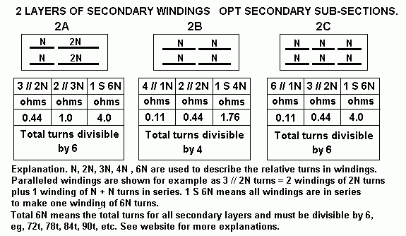
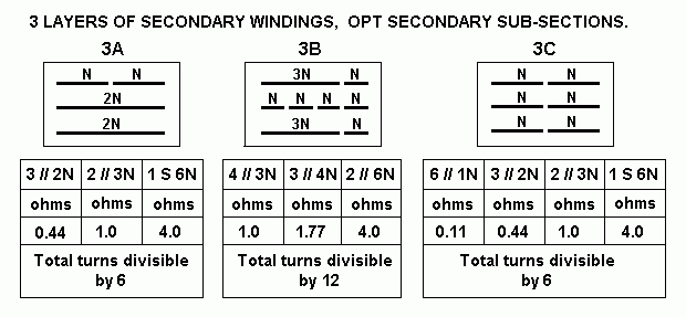
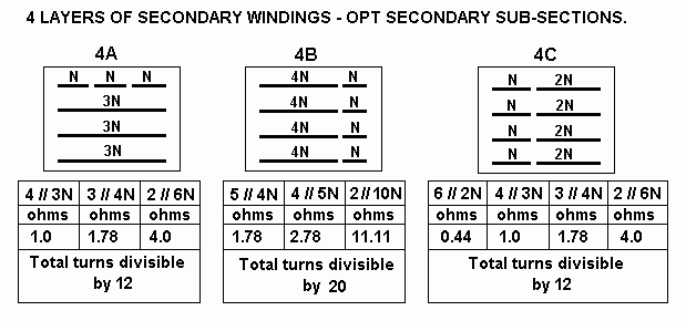
Fig 8,9,10,11,12 for possible OPT secondary windings sub-divided for many load matches.

Table 10. Nomex 401 properties.

-------------------------------------------------------------------------------------------------------
(A). RDH4, SE amp history, trends and preferences.
Much good advice is found in the Radiotron Designer's Handbook, 4th Edition, 1955. It is a difficult book
to read for anyone not used to understanding basic issues of electron flow in L, C and R circuits.
One must begin with basics, including just how tubes work.
A good deal of single ended pentode and triode circuits in RDH4 has been on preamps which have such
high linearity at low levels that there is no need for complex balanced or PP designs. Hardly anyone in
1955 thought that real hi-fi could be had from a single ended power design design. But millions of amplifiers
with one power pentode or beam tetrode or triode were used in AM radios and radio-grams for the 45
years prior to 1965.

Triodes were used for all audio power amps up to about 1933 when power beam tetrodes and pentodes
were invented and which gave nearly twice the audio power of a triode for the same idle power dissipation.
In 1960, many people listened to radio or TV broadcasts where one 6V6, EL84, 6M5, 6BM8 gave up to
about 3W from a class A single ended audio amp. The THD & IMD was tolerable at low levels with
sensitive speakers using very low power.
Very occasionally a radio-gram manufacturer may have used an 807 which had been bought in bulk from
military disposal stores after WW2 when millions of 807 were over produced, delighting many ham radio
operator and audio DIYers until about 1965 when old WW2 stocks finally ran out.
The brighter audio DIYers found the 4W available from an SE 807 in triode mode sounded far better than
4W from a 6V6 beam tetrode. I agree with them, and when repairing or restoring old radios I often used an
EL34 in triode mode instead of a 6V6 in beam tetrode without NFB.

For serious hi-fi after 1950, and for more than 4W, mainly PP circuits were used, and 10W+ was easily
available in class AB1 from a pair of 6BM8,  6GW8, 6BQ5, 6V6 in "Ultralinear", UL, configuration.
It was cheaper to make a 10W PP amp than make an amp with a single 807, 6L6, or EL34. PP amps
were found in deluxe TV sets and some hi-fi amps; SE was considered old fashioned.

Despite commercially profitable trends and fickle public tastes, a few hi-fi fanatics were not concerned
about the costs, and found their ears told them an 807, 6L6, EL34 strapped as a triode could make a far
better sounding 4W than the first 4W from any pair of little tetrodes or pentodes in PP such as 6AM5,
EL84, 6V6, 6F6, 6AR5 etc.
The best 4W of SE power can be had from a lone 2A3, and the 300B can make a magnificent 9W, and
a single 6550 or KT88 in triode mode also excel.
I have had a kitchen AM tube radio since I designed and built it in 1999. It has been reliable,
with modifications to improve it since 1999. I am presently using a 1970s Audio Reflex AM-FM tuner to
give mono FM. The AF power amp is 12AX7 driving EL34 in SE triode with all hi-fi principles applied,
including 12dB GNFB. The RF and IF and detector tubes in AM radio tuner section sound better than the
AM tuner in Audio Reflex or any other 1970s AM section using bjts and primitive circuitry.
AM had become unfashionable by 1975, but when AM reception is done well, it can sound very pleasing
indeed. My AM tuner has 9kHz bandwidth, and THD > 1%.

In Japan after WW2, there were quite a number of audio enthusiasts who liked SET amplifiers.
A Mr Kondo San of Audio Note in Japan brought renewed interest in SE triode amps in the 1990s.
He died in Jan 2006 after 30 years of building amplifiers, and he left a legacy worth preserving. I have built
several high power SE amps :-
monobloc845se55.html
monobloc-se32-13e1-cfb-2012version.html
se35cfb-monobloc.html

My method for SE OPT design is based on the theory in the RDH4 or other sources I collected since
1993. After winding many SE OPTs with full power bandwidth from 20Hz to 70kHz, I feel well qualified to
speak from experience. The list of logic steps involved in producing the best possible OPT is based on
designing for low winding losses, core saturation at full power at 20Hz or lower, and adequate interleaving
to extend the HF response up to at least 70kHz by minimizing leakage inductance and shunt capacitance.
Winding window is well filled to give low winding resistance < 10%, and secondaries are arranged to allow
strapping windings for 3 or more useful secondary loads.

The design for SE OPT has some common features to Push Pull OPTs, but I have tried to give enough info
in this page to no need to refer to PP pages for reference. SE OPT design is for only purely class A1
operation and does not have to cope with complexities of PP class AB operation.

(B) Tables 1, 2, 3 for SE operation from some common power tubes :-

Table 1. SE Pentode, Beam Tetrode, CFB, UL.
Tube type
number
SEP, SEBT,
50% UL,
Local CFB
Max
Idle
Pda W
Ea
Vdc
a-k
Ia
Idc
mA
Max
Po
W
Effic
iency
%
Eg2
g2
to k
Ig2
mA
dc
Pdg2
W
RLa
max
Po
EL84
and 6V6
SEP, CFB,
Eg2 < Ea.
12
12
12
300
275
250
40
43
48
5.4
5.2
4.8
45
43
40
270
235
200
5
5
5
1.2
1.2
1.0
6k7
5k7
4k7
EL84
and 6V6
SEUL,
Eg2 = Ea
12
12
12
300
275
250
40
43
48
5.2
4.9
4.7
43
41
39
300
275
250
5
6
7
1.2
1.4
1.5
6k7
5k7
4k7
EL86 SEP, CFB,
Eg2 < Ea.
12
12
12
250
225
200
48
53
60
5.4
5.2
4.8
45
43
40
200
200
200
4
5
6
0.8
1.0
1.2
4k7
3k9
3k0
EL86 SEUL,
Eg2 = Ea
12
12
12
250
225
200
48
53
60
5,2
4.9
4.7
43
41
39
250
225
200
5
6
7
1.3
1.4
1.4
4k7
3k9
3k0
807, 6L6GC,
KT66, 5881
SEBT, CFB,
Eg2 < Ea.
21
21
21
400
350
300
53
60
70
9.5
9.0
8.4
45
43
40
300
270
250
4
5
6
1.2
1.4
1.5
6k8
5k3
3k4
807, 6L6GC,
KT66, 5881
SEUL,
Eg2 = Ea
21
21
21
400
350
300
53
60
70
9.5
9.0
8.4
45
43
40
400
350
300
4
5
6
1.6
1.8
1.8
6k8
5k3
3k9
EL34,
6CA7
SEP, SEBT,
CFB,
Eg2 < Ea
21
21
21
400
350
300
53
60
70
9.6
9.5
8.4
46
45
41
270
270
270
7
8
9
1.9
2.2
2.4
6k8
5k3
3k4
EL34,
6CA7
SEUL,
Eg2 = Ea
21
21
21
400
340
300
53
62
70
9.5
9.0
8.4
45
43
40
420
350
270
8
9
10
3.3
3.2
2.7
6k8
5k0
3k4

Table 2. SE Pentode, Beam Tetrode, CFB, UL.
Tube type
number
SEP, SEBT,
40% UL,
Local CFB
Max
Idle
Pda W
Eadc
+Vdc
a to k
Ia
mA
dc
Max
Po
W
Effic-
iency
%
Eg2
g2
to k
Ig2
mA
dc
Pdg
W
RLa
max
Po
6550, KT88 BT, UL,
CFB,
Eg2 < Ea
28
28
28
28
450
390
330
270
62
72
85
104
12.6
12.0
11.5
11.0
45
43
41
39
300
270
270
270
5
5
6
7
1.5
1.4
1.6
1.9
6k5
5k0
3k5
2k3
6550, KT88 UL,
Eg2 = Ea
28
28
28
28
450
390
330
270
62
76
90
110
12.0
11.5
10.9
10.4
43
41
39
37
450
390
330
270
6
7
8
10
2.7
2.7
2.7
2.7
6k5
5k0
3k5
2k3
KT90, KT120 SEBT,
CFB,
Eg2 > Ea
33
33
33
33
450
390
330
270
74
85
100
123
14.8
14.3
12.9
12.2
45
43
39
37
300
270
270
270
5
6
7
8
1.5
1.6
1.9
2.2
5k5
4k2
3k0
2k0
KT90, KT120 SEUL,
Eg2 = Ea
33
33
33
33
450
390
330
270
74
85
100
123
14.8
13.6
13.0
12.2
45
43
39
37
450
390
330
270
5
6
7
8
2.3
2.4
2.3
2.2
5k5
4k2
3k0
2k0
13E1 SEBT, CFB,
Eg2 < Ea
72
72
72
72
550
460
380
300
130
156
189
240
32.0
30.0
28.1
25.2
45
41
39
35
220
200
180
160
6
5
5
4
1.4
1.0
0.9
0.7
3k8
2k7
1k8
1k2
13E1 SEUL,
Eg2 = Ea
70
70
70
375
350
325
186
200
215
27.3
25.9
22.1
39
37
35
375
350
325
13
12
10
5.0
4.2
3.3
1k8
1k6
1k4

Table 3. SE TRIODE.
Tube type
number
SE triode
g2 to
anode. 
Max
Pda +g2
idle W
Ea
+Vdc
a to k
Ia +
Ig2
mAdc
Max
Po W
Effic-
iency
%
Ra at
Eg1=
0Vdc
RLa
for
max Po
EL84,
Triode
12
12
12
350
320
280
34
37
43
3.4
3.0
2.3
28
25
19
2k2
2k1
2k0
5k9
4k4
2k5
EL86
Triode
12
12
12
250
225
200
48
53
60
3.5
3.1
2.7
29
26
22
1k1
1k0
0k9
3k0
2k3
1k5
6V6
Triode
12
12
12
370
340
317
32
35
38
3.4
3.0
1.7
28
25
15
2k5
2k4
2k3
6k5
4k9
3k7
807, 6L6,
KT66, 5881
Triode 22
22
22
22
500
450
400
350
44
49
55
63
7.3
6.7
5.5
4.2
33
30
25
19
1k9
1k8
1k8
1k7
7k8
5k6
3k7
2k2
6CM5, EL36 Triode 18
18
18
375
350
325
48
51
55
7.6
7.5
7.4
42
41
40
0k6
0k5
0k5
6k6
5k8
4k9
EL34, 6CA7 Triode 23
23
23
23
450
420
390
360
51
55
59
64
7.5
7.3
6.9
6.6
33
32
30
29
1k2
1k1
1k1
1k0
7k4
4k8
4k0
3k3
6550, KT88 Triode 30
30
30
30
500
450
400
350
60
67
75
86
11.0
11.0
10.0
8.4
36
36
30
28
1k0
0k9
0k9
0k9
6k3
4k9
3k5
2k3
KT90 Triode 33
33
33
33
500
450
400
350
66
73
83
94
13.4
12.6
11.8
10.3
39
38
35
31
0k7
0k7
0k7
0k7
6k2
4k8
3k5
2k4
KT120 Triode 40
40
40
40
500
450
400
350
80
88
100
114
15.6
14.7
13.5
11.0
39
36
33
27
0k7
0k7
0k7
0k7
4k9
3k8
2k7
1k7
45
Real
Triode
8
8
8
270
240
210
29
33
38
2.4
2.0
1.4
30
25
17
1k8
1k8
1k8
5k7
3k7
1k9
2A3 Real
Triode
12
12
12
300
275
250
40
43
48
4.4
4.2
3.9
36
35
32
0k9
0k9
0k9
5k7
4k6
3k4
300B Real
Triode
28
28
28
420
380
340
66
74
82
10.8
10.0
9.3
37
35
33
0k7
0k7
0k7
5k0
3k8
2k8
845 Real
Triode
75
75
75
1,100
950
800
68
78
93
27.1
23.7
18.2
36
31
24
2k2
2k2
2k2
11k8
7k8
4k2
GM70
Real
Triode
75
75
75
1,100
950
800
68
78
93
29.1
26.1
22.0
38
34
29
1k8
1k8
1k8
12k6
8k6
5k1
13E1
Triode 70
70
70
375
350
325
186
200
215
24.0
23.0
22.0
34
32
31
0k3
0k3
0k3
1k4
1k2
1k0

NOTE. Interpreting 3 tables :-
Tube Type. Includes those most commonly used plus a few which are uncommon such as EL36,
6CM5, 13E1 which are no longer made.

SE = Single Ended Mode = One tube only, or more than one paralleled.
SEP = single ended pentode, SEBT = single ended beam tetrode, both with cathode bypassed to 0V
with R+C network for Ek cathode bias, or direct to 0V for fixed -Vdc grid bias. SEP or SEBT has
screens fed from fixed Eg2 usually lower than B+ to anodes. The screens are bypassed with
electrolytic C to cathode or 0V.

CFB = Cathode Feedback windings used on OPT. CFB windings are usually between 10% to 25%
of the total primary turns on OPT, and have same anode and signal current. Thus up to 25% of the
Va-k signal Vac appears at cathode to give about 12dB local series voltage negative feedback
which reduces Ra of pentode or beam tetrode from say 25k0 to less than triode, maybe 700r.
Screen Eg2 for SEP or SEBT is lower than anode B+ but screens are bypassed with electrolytic
C to 0V.
The CFB mode is also known as Acoustical, as used in early Quad-II PP amps, but it works very
well in SE amps. Sometimes g2 is taken to taps on anode winding for say 25% of Va-k signal to give
some screen feedback like the UL connection.

SEUL = Single Ended Ultralinear, where g2 is taken to taps on anode winding where the portion
of B+ to screen winding is not more than 66% of total anode turns. Eg2 becomes equal to Ea
because the screen feed is from OPT primary winding.

SET = Single Ended Triode = Triode strapped multigrids with g2 and g3 is tied to anode or where
the tube is a real triode like 300B.

(C) BIASING of grid g1 is not mentioned in tables.
"Cathode Biasing" is The Best way to bias SE amps is to have a separate parallel Rk and Ck with
say 470r 5W  +  470uF between cathode and 0V. The grid g1 has say 100k between g1 and 0V
so the Vdc at g1 is 0V. Choosing the correct value for Rk is very important so that Iadc x Ea
between a and k = idle Pda.

To easily measure Iadc, measure Vdc between cathode and 0V, Ek. Ikdc = Ek / Rk.
The Ig2dc must be measured by Vdc across the stopping Rg2 between between g2 and the screen
supply bypass C.
This is often 270r, so if idle Vdc across Rg2 = 1.62Vdc, then Ig2dc = 1.62 / 270r = 6mAdc.
The Iadc may be calculated Iadc = ( Ek / Rk ) - Ig2dc. Idle Pda = Ea x Iadc only, and it does not
include Pdg2, which is Eg2 x Ig2dc, in Watts. If the Idle Pda is too high, then increase Rk value
until you get the correct idle Pda.
The Pda shown in my tables is the absolute maximum recommended for SE operation and is less
than the max Pda rating you see printed in tube data sheets. The exceptions are for EL84 and 6V6
where usable Pda and Pda max = 12W. Pda at idle may be lower than I recommend to give longer
and more reliable tube life.

FIXED BIAS is also used where an adjustable -Vdc rail supply feeds a negative Vdc to g1 through
a baising resistor or perhaps through a secondary winding of an IST. Cathode is connected direct to
0V but usually with Rk = 10r0, 5W to allow measuring Iadc + Ig2dc easily and safely while adjusting
the -Vdc bias to g1.
Fixed bias gives no automatic regulation of Iadc by means of the local dc current FB with cathode
bias so I cannot recommend fixed bias for any SE amps.

Fixed bias was more popular in the past. A 300B with idle Pda 26W, Ea = +400Vdc, Ia = 65mAdc
needs Eg1 bias = -85Vdc. If cathode bias is used, B+ might be +490Vdc, and you must not use
450V rated C, but have 3 x 350V rated C in series. Rk is 1k3 and its heat = 5.5W, and the bypass
C should be 470uF x 200V rated.
Thus many ppl settled for fixed bias because no cathode R+C was needed and the B+ could be
+400Vdc and 450V rated C were just fine. This is OK if you have only 1 tube per channel but for
SE 35, there are 8 output tubes for 2 channels and nobody enjoys 8 bias adjustments.

Use of any power tetrode or pentode such as KT88, 6550 in triode mode or SEUL mode also means
the Eg1 is going to be high. But pentodes or tetrodes don't need to be used as triodes and can work
well with lower B+ than when triode or UL connected, so Eg1 is not too much where Ea = Eg2 for say
UL mode. In CFB mode the Eg2 can be a lot less than Ea, thus reducing the required Eg1, as seen in
SE35. Cathode bias is always OK because you get good Iadc regulation with Rk, all tubes will have
similar Iadc, and Ek is low and heat in Rk is low.

The higher Pda, the higher the operating temperature and shorter the tube life. If idle Pda is different to
what my tables show, all information for anode loading and Po etc must be re-calculated.
If more than one SE tube is used and you have 2,3,4 paralleled, there is NO NEED to have such high
idle Pda and it may be reduced -20%. 1 x EL34 may have idle Pda 24W. But with 4 x EL34, its best to
have Pda = 19W for each, and you get much longer tube life and the multiple tubes can still give audio
Po = 42% of total idle Pda which will be *enough* because nobody needs more than 35W from 4
tubes each with idle Pda about 21W. See SE35cfb

(D) Calculate anode loads for maximum SE anode Po.

PENTODE RLa for SEP Po is calculated RLa = 0.9 x ( Ea / Iadc ), where Ea is Vdc from anode to
cathode and Iadc = Ikdc - Ig2dc.

RLa for SE pentodes and beam tetrodes may also be calculated RLa = ( Ea / Iadc ) - ( 2 x Rd ) where
Rd is the "diode line" resistance value. The name diode line is an odd conventional term but all tubes have
a diode line the control grid g1 is at same potential at cathode, and diode line resistance
= Ea change / Ia change for low values of Ea between 0.0V and 100V. With pentodes or tetrodes, the
diode line resistance is measured with a fixed Eg2 at more than 100Vdc above cathode, but with triodes
and multigrids connected as triodes the screen is tied to anode and the triode diode line is typically a higher
R value than multigrids, ie, it has less slope. There are some complex mathematics governing the shape of
Ra curves and diode lines and there is no need to include all of them here for load calculations.

A typical Rd value for many pentodes and beam tetrodes = 200r.
For most power pentodes and beam tetrodes RLa can simply be RLa = ( Ea / Ia ) - 400, where Rd is
not known accurately but is between 150r and 300r, say 200r.  

TRIODE RLa for SET Po is calculated as RLa = ( Ea / Ia ) - ( 2 x Ra ) where Ra is the straight line
calculation for the first part of the diode Ra diode curve for where Eg1 bias = 0Vdc. This Ra curve is the
diode line for a triode which limits the Ea swings achieved with grid 1 voltage becoming equal to cathode
voltage. In 95% of all amps the triode grid input impedance changes from being megohms where Eg1 is
negative in respect to cathode Ek. But where grid g1 becomes higher than Ek, its input resistance plummets
to a k or two, because the grid acts like a diode. The sudden reduction of g1 Rin causes the gain of the
driver tube to reduce to very little, ie, the change of g1 R1 limits or clips the Vac waves made by driver.
But in 1930s before pentodes and tetrodes were widely used, grids of power triodes were driven positive
with a driver amp using smaller power triodes able to work into any load above 1k0. The more modern
approach is to use a direct coupled cathode follower to drive the output tube grid so it allowed triode to
make a similar of power in class A2 as a pentode or tetrode with the same idle power. The disadvantage
is that the A2 triode requires the cost of an extra tube, and the output tube grid can overheat, so A2 is in
fact a big worry and expense for what is a small power increase.
Therefore is is more sensible to accept that you cannot get SE triode efficiency much above 30% for most
real triodes like 45, 2A3, 300B, 845 etc, but the power you do get is good because it has low odd H
products and anode Ra is lower than RLa- so DF is good and often above 3 without any NFB.

Maximum anode Po for pure class A1 where THD < 2% for the loads is calculated
SE Po = [ 0.5 x ( Iadc squared ) x anode RLa ] Watts.
This depends on a total of 20dB NFB by whatever means of external loops.
Less Po is produced without NFB because THD is higher, > 5%, and Ea swings are unequal, and Iadc
changes due to 2H and 3H production.
Anode efficiency is calculated Efficiency % = ( 100% x max anode Po / Pda at idle ) %.

The tables are a GUIDE for OPT design. The Ea and Ia determine the load value which gives the highest
power at clipping. Raising Ea and lowering Ia for the same Pda will allow a higher RL, and lowering Ea and
raising Ia will allow a lower RL. Thus the Ea and Ia may be adjusted to suit a given RLa or to suit an OPT
which is available.

NOTE. For Parafeed connection where a high value choke inductance is used to bring the Idc to the tubes,
and the OPT primary is coupled to the anode with a capacitance, the OPT may be designed using the method
for PP OPT calcs.
---------------------------------------------------------------------------------------------------------
(E) Design OPT for 1 x EL34 pentode with or without CFB.

From Table 1, EL34 operating conditions for long tube life :-
The output power is for the anode, and it will depend on 20dB NFB to keep the THD < 1%, and if OPT
has total Rw loss of 7%, max Po at secondary = 8.8W.

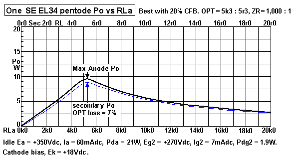
Graph 1. Po vs RLa, 1 x EL34.
graph-EL34-se-pentode-po-vs-rl-ea-350V.gif
Graph 1 shows the maximum anode Po for various RLa loads available from ONE SE EL34 or 6CA7 in
Pentode mode or CFB mode. The OPT could have ZR = 1,000 : 1, with load ratio = 5k3 : 5r3.
Speaker loads which are sold as nominally "8r0" may vary between 4r5 and  20r0 for different frequencies.
The Po = 6.6W for 8r0. But where speaker Z dips to 5r3, anode Po = 9.5W, for 8.8W at Sec.
There is useful Po at Sec of at least 6.6W between 3r8 and 8r0. Notice that OPT loss % is highest when
RL is lowest; with 2r0, loss = 19%, but 2r0 speakers will not be used. Losses reduce with increasing
Sec RL, for 10r6 loss = 3.5%. There is no need to worry about loss in a small amount of unavoidable
series resistance.
The OPT with 5k3 : 5r3 or up to 6r0 is the simplest way to arrange one EL34 and OPT so that almost all
loads above 4r0 could be powered. It would be better to have OPT with 5k4 : 4r0, 8r0 and perhaps 16r0
to allow change of  sec winding connections to better suit the full range of available speakers in the world.
If you try one EL34 set up with 20% CFB, you may find it handles music as well as a single 300B which is
supposed to be the Gold Standard for SE performance. But there are limits to sound level with such a small
amount of Po with a speaker of only 85dB/W/M sensitivity. A speaker such as a Tannoy dual concentric
rated for 96dB/W/M will sound OK with one EL34 or one 300B.

The Nominal OPT primary load RLa for SE amps can be 25% above the RLa for max Po. So for 1 x EL34
RLa may be between 5k4 and 6k8. The OPT should have at least a fixed sec winding for 5r0 or have sec
with multiple sections able to be strapped for 4r0, 8r0, 16r0.

So an OPT of say 6k0 : 4r0, 8r0, 16r0 will be sufficient and with various secondary links or taps to get the
3 different Sec load matched for the one ideal load for the tube.
-----------------------------------------------------------------------------------------------------------------
(F) Pentode AND Triode curve for Eg1 = 0V, different Eg2. 
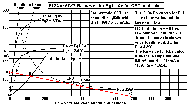
Fig 1. Ra curves for Eg1 = 0V, Eg2 = +350Vdc, or +250Vdc.
EL34-6CA7-Ra-curve-Eg1-0V+Rd-120r-280r.gif
Fig 1 shows the EL34 Pentode Ra curves for Eg1 = 0V and 2 values for Eg2. There is also Triode Ra curve
for Eg 0V. There is one loadline with RLa value = 4,850r for both CFB and triode operation,
CFB has Idle Q at Ea = +357V x 63mAdc and triode has idle Q at +400V x 58mAdc.
CFB Pda = 22.5W not including Pdg2, Triode Pda = 23.2W including Pdg2.

Maximum rated Pda for 25W is shown, showing that the idle Ea and Iadc is below this Pda max curve.
EL34 data sometimes indicates max Pda = 28W, and other data says 25W, but triode Pda may include
Pdg2 because both anode and screen work together to make the Po.
EL34 should never ever have idle Pda + Pdg2 = 28W, which is a max rating and guide for PP class AB
where Pda may reach 28W but at idle the Pda may be 14W. With SE amps, the output power depends
on idle Pda and cannot ever exceed about 42% of idle Pda at output. 

Triode Rd = 119V / 116mA = 1,026r.
For maximum Po, Triode RLa = ( 400V / 58mA ) - ( 2 x 1,026 ) = 4,845r. RwP+S at Primary could
be 7% of primary RLa for total anode load of 5,184r.
Triode anode Po = 0.5 x 0.058 x 0.058 x 5,184r = 8.7W and Secondary Po anode Po -7% = 8.1W,
Triode overall efficiency = 100% x 8.1W / 23.2W = 34%, a fair result.

For pentode operation with 20% CFB, the same RLa load can be used but RLa may intersect Rd line
point E. The idle point cane be midway between E and C so Q point is at Ea +358V x 63mA for Pda
= 22.55W. The screen Eg2 can be +250Vdc and Ig2 = 4mA, and Pdg2 = 1W = OK.
CFB anode Po = 0.5 x 0.063 x 0.063 x 5,184r = 10.28W and Secondary Po = 9.5W, and pentode
CFB overall efficiency = 100% x 9.5 / 22.55 42.1%.
What you may get could vary +/-5% depending on slight EL34 differences, Ea and Ia differences and
OPT Rw losses. 
 
Measuring Rd slope is difficult, and many data sheets display incomplete Ra curves for low Ea swings
below 100V. But Rd MUST have a value.

(G) Calculate RLa, Po, etc, for Pentodes and Beam Tetrodes only.
Without load line analysis :-
Example 1:- EL34 pentode with Pda = 22W, Ea = 350V, Ia = 63mA.
For maximum possible Po, RLa = 0.9 x Ea / Iadc = 0.9 x 350V / 0.063A = 4,999r, and this
is close to load line in Fig 1.

More complex formula 2, RLa = ( Ea / Iadc ) - ( 2 x Rd ), ohms. For this case, assume Rd = 200r
for 20% CFB use, or with 50% UL. RLa = ( 350V / 0.063A ) - ( 2 x 200r ) = 5,155r.
Rd is between 120r for pure pentode and 280r for 50% UL, and estimated at 200r for 20% CFB.

Both formulas give nearly the same answer.

If the RLa is lower than RLa for max Po, then Po max = 0.5 x Idle Idc squared x lower RLa.

If RLa is higher than RLa for max Po, then Po max = 0.7 x ( idle Ea - Ea min ) squared / higher RLa.
The peak negative going Ea swing can be calculated :- Vapk = Ea - { [ ( idle Ea / RLa ) + Iadc ] x Rd }.

Consider RLa = 7,000r, Va pk = 350V - { [ ( 350V / 7,000 )A + 0.063A ] x 200r }
= 350V - { [ 0.05A + 0.066A ] x 200r }
= 350V - 22.6V
= 327.4pk.
Anode Po = 0.5 x Va pk squared / RLa = 0.5 x 327.4V squared / 7,000r = 7.65W, Rw loss 7%
reduces this to 7.1W 

From all this, it is difficult to be completely precise about calculating loads because the Rd line R value
may not able to be known. However, if RLa calculated for max Po = 5k1, the OPT load can be
calculated Primary RL = calculated RLa - estimated total Rw = 5k1 - 7% = 4,743r, or slightly higher,
but not lower. 

Conclusion for ONE EL34 pentode with Ea 350V and Iadc = 63mAdc, OPT can be 4k8 : 4r0, 8r0,
16r0. A 5k0 : 4r0, 8r0, 16r0 is probably available from a manufacturer but is will not have a 20% CFB
winding but it may have a 40% UL tap. If the only OPT choices choices are say 4k0 or 7k0 for primary
and rated for 10W, they can do OK, and the idle Ea and Ia can be altered to suit the OPT.

Each nominal secondary load match is suited to same nominal average speaker loads which may vary by
-30% or + 300%. When OPT sec is strapped for 5k0 : 4r0, a 4r0 speaker can vary between 2r8 to
16r0, due to impedance reductions at crossovers and resonant peaks at bass F, so anode load varies
between 3k5 and 20k. an EL34 will cope OK but not if you you use a lower Z speaker, or use the "4r0"
speaker at 8r0 terminals where anode load could become 1k8 to 10k. Where the speaker Z goes too
low, THD, IMD, damping factor and winding losses all become far worse. The EL34 does not mind a
high RLa with only worry being less max Po, but it does not like RLa that is too low.  
--------------------------------------------------------------------------------------------------------
(G) Calculate RLa, Po, for Triodes only.
Without loadline analysis.
Example. For single EL34 in TRIODE, Pda+Pdg2 = 23W, Ea = 400V, Ia+Ig2 = 58mAdc,  idle Pda = 23W,
Calculate Triode RLa for maximum :-
Po = [ Ea / ( Iadc+Ig2dc ) ]r - [ 2 x Ra from step 2 ]r = [ 400V / 58mA ] r - [ 2 x 1,026r ] =
6,896r - 2,052r = 4,844r. My loadline shows 4,850r and error < 0.7%, OK.
 
The SAME load value for Triode as for CFB can be used, but idle Ea is higher, Idle Ia is lower
for about same idle Pda, and the triode gives less max Po about 7.1W at Sec output.
-----------------------------------------------------------------------------------------------------------
(H) MORE LOADLINES FOR SE EL34.
loadline analysis 1 x EL34 or 6CA7 with some simple calculations.
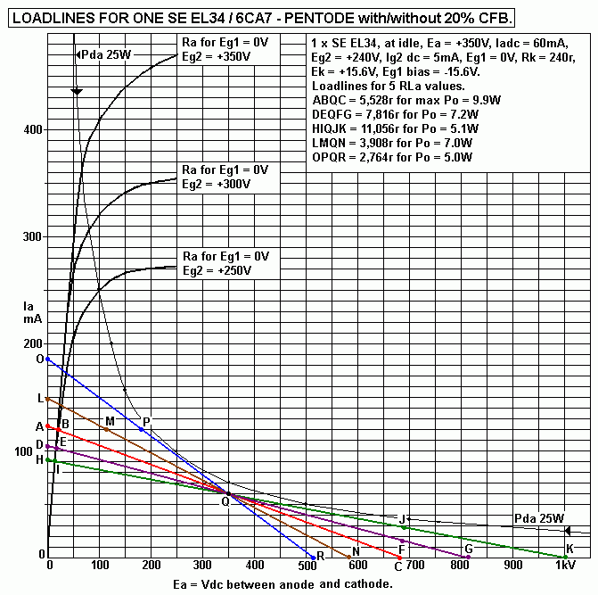
Fig 2. Five Loadlines, 2k7 TO 11k0 for EL34 with CFB, Ea 350V, Ia 60mAdc.
graph-EL34-pentode-CFB-loadlines-Ea350V-Pda-21W-350V.GIF
Fig 2 shows the diode line Ra curves for Eg1 = 0V for EL34 / 6CA7 for 3 values of Eg2, and copied
from tube data sheets from 1957. Recently made EL34 or 6CA7 in Russia since 2000 are similar.
Ra curves for other values of Eg1 are not required for loadline analysis, and Eg2 for CFB need not be
known.
Choose idle Pda = 21W and idle Ea = +350V. Idle Ia = 21W / 350V = 60mAdc. 

Plot loadlines for 1 x EL34 SEP, with 10% to 20% CFB or 40% to 50% UL.
1. Plot point Q at Ea = 350V x 60mA.

2. Plot the loadline which will give maximum audio power. Plot point B at 2 x idle Idc = 120mA on Ra
diode curve for Eg1 = 0V. The Ra curve is nearly straight line with R value 167r between Ea 0.0V
and 50V.
Point B should be at Ea 20V x 120mA, and is at Ea minimum.
Calculate Ea swing = +350V - 20V = 330Vpk.
Calculate RLa = Va pk / Ia change = 330V / 0.06A = 5,500r.

3. Calculate Ea maximum where Ia = 0.0mA = 350V + 330Vpk = 680V.
Plot point C for 680V x 0.0mA.

4. Draw line from C thru Q and B and plot point A where line intersects axis for Ea = 0V.
ABQC is the line for maximum possible SEP class A for EL34.
This line should be straight, and pass thru C,Q, B. If line does not pass thru these 3 points you have
made a mistake. 
Drawing a diagonal line in MSPaint will always give a straight line.
But a straight ruler may be held  across PC screen to view the line without drawing it, and erasing it
if its wrong.

5. Calculate Max Po = 0.5 x Iadc squared x RLa = 0.5 x 0.06 squared x 5,500r = 9.90W.
Max Po also = 0.5 x Vapk squared / RLa = 0.5 x 330V squared / 5,500r = 9.90W.
Theoretical anode efficiency = 100% x Po / Pda = 100% x 9.9 / 21.0 = 47.1%
Real anode Po will always be less. Max Po is best measured with 20dB NFB, and where
THD < 1%.
Expect anode efficiency = 45%, anode Po max = 9.45W. Without any NFB at all expect THD at
clipping = 10%, and max Po = 9W approx.

6. Draw additional loadlines for RLa 5,500r x 0.50, x 0.71, x 1.41, x 2.0, 
Additional RLa = 2,750r,  3,905r, 7,777r, 11,000.

7. Draw loadline for 7,777r.
For all loadlines higher than RLa for max Po, the Ia swing is always less than +/- Iadc, and load line
position must be calculated :-
Calculate Ia point on Ia axis where Ea = 0.0V = ( Ea / RLa ) + idle Iadc
= ( 350V / 7,777r ) + 60mAdc
= 45.0mA + 60mA = 105mA. Plot point D on Ia axis for Ea = 0V.
Calculate for a point on Ea axis where Ia = 0.0mA if the Ia change = idle Iadc.
Va pk change = RLa x Iadc = 7,777r x 60mA = 466V.
Ea at idle = +350V, and could swing up +466V pk with Ia change 60mA.
Theoretical Ea max = 350V + 466V = +816V.
Plot point G at 816V x 0.0mA.

8. Draw a straight line from G thru Q and to D. This line should pass through the 3 points.
Plot point E where the line crosses Rd. Read off the Ia at E = 103mA. Ea at E = Rd x 103mA
= 167r x 103mA = 17.2V.
The -Va pk swing = 350V - 17.2V = 333V pk. For linear operation, the +/-Va swings are equal so
+Va pk swing = 333V and maximum Ea at +Va pk = Ea + Va pk swing = 350V + 333V = 683V.
Plot point F along straight line G-Q-D at 683V x 17mA
DEQFG is loadline for RLa = 7,777r
Max Ia swing = Ia max - Iadc = 103mA - 60mA = +/- 43mApk.
Max anode Po = 0.5 x 0.043 squared x 7,777 = 7.19W.

9. Use similar steps to plot loadline HIQJK for RLa = 11,000r.
H is at Ia = ( 350V / 11,000r ) + 60mA = 92mA, and point I is at 15V x 90mA and Ea swing = 335V.
Ia swing = +/- 30mApk, so Ea max at J is at 685V x  30mA and K is at 1,010V which will not be
reached during normal operation.
If RLa is high enough, the loadline becomes more horizontal and it becomes impossible to plot the point
higher than K. But the point J can always be plotted and is found at Ea = Idle Ea + ( RLa x Iapk swing ).
Po for RLa 11,000 = 0.5 x 0.03 squared x 11,000r = 4.95W.

10. Draw loadline for RLa 3,905r, LMQN.
For all loads less than RLa for max possible Po, position for point L on Ia axis will be
= ( Ea / RLa ) + idle Iadc = ( 350V / 3,905r ) + 60mA  = 89.6mA + 60mA = 149.6mA.
Plot point L at 150mA on Ia axis. 
For all RLa less than for max Po, Ia swing max = +/- Iadc = +/- 60mApk.
Therefore Ea min = Ea - ( RLa x Iadc ) = 350V - ( 3,905r x 60mA ) = 350V - 243V = 107V, and
plot M at 107V x 120mA.
Plot N for Ea max where Ia = 0.0mA = Ea + ( RLa x Iadc ) = 350V + 243V = 593V x 0.0mA.
Draw straight line from N to L and it should pass through M and Q.
Max anode Po for RLa 3,905 = 0.5 x 0.06 squared x 3,905r = 7.03W

11. Draw loadline for 2,750r Use the same procedure for step 10 for 3,905r. You should get loadline
OPQR.
The Po = 0.5 x 2,750r x 0.06 x 0.06 = 4.95W.

12. The results for clipping Po available from the five RLa loads may be plotted on a graph for Po vs RLa
and you will find your graph will look very similar to results shown for Graph 1 above.

NOTE. The load range between 0.5 and 2.0 x 5,500r for max possible Po gives a useful amount of
audio power above approximately 4.6W up to 9W approx. While this is very low Po, it is surprising
how good it sounds with well chosen sensitive speakers with ideal nominal Z giving anode load of 5,500r
+/- 30%.
4 x EL34 in parallel with same working conditions as above for each EL34 give 18W to 35W with
RLa 688r to 2,750r.

NOTE. There are "knees" in the 3 curves for Ra at Eg1 = 0V for each value of Eg2. All knees are well
above 2 x idle Iadc which is the maximum load current which can ever exist in pure class A operation.
Having high Eg2 becomes necessary for PP class AB operation where Iapk can be 450mA for max Po
> 50W from only 2 x EL34.

But for UL connected pentodes and beam tetrodes, Eg2 = Ea.
The knee of the UL Ra curve is high like the Eg2 curve for Eg2, but only if the UL tap is at less than
60% of the total anode turns in OPT primary. Using UL taps at 60% give Ra curves which begin
to resemble triodes which limit the peak negative going Va pk swings in PP AB amps, but maybe not
much in SE class A amps with low max Iapk. Cathode biasing for UL or triode requires a much
higher Ek and higher Rk, which has advantage of good control of idle Iadc, but for same OPT used
for CFB, the triode Ea = 400V, and B+ will be +460Vdc approx.
The best UL tap position for SEUL operation for EL34 is 40% to 50%. The use of say 12.5% of
CFB plus say 20% UL taps is also possible for low THD and detailed sound.

Fig 2 shows 5 loadlines for RLa and explains the loadlines for one EL34 of 4 parallel EL34 in amp at
SE35cfb. See the schematic SHEET 1 - 2011. More details about operation are explained at the page.
The principles for use of 1 x EL34 can be applied for the use of any number of of parallel EL34.

From SE35cfb and SHEET 1 - 2011, the measured Va-k = 228Vrms.
Confirm Idle conditions for 4 x EL34 in parallel :-
Ea  = ( B+ +380Vdc ) - ( Ek +18.5Vdc ) - ( Vdc across anode portion OPT Pri 8Vdc ) = +353.5Vdc.
Ia = 4 x 60mAdc = 240mAdc, Pda = 84.8W. Pda for each EL34 = 21.2W.
Eg2 = ( B+ +280Vdc ) - ( Ek +18.5Vdc ) - ( Vdc across 220r +1.7Vdc ) = +259.8Vdc.
Ig2 = 30mAdc, Pdg2 = 7.8W.
Total Pda+g2 = 92.6W = 23.15W for each EL34, and this is 5W less than max rating for Pda+g2.

The OPT has TR = Np 1,952t : Ns 3//124t = 15.742 : 1 with ZR = 247.8 : 1.
The nominal sec load = 5r0, nominal Primary RLa = 1,239r, and the total winding resistance
RwP+RwS = 143r, and total of nominal RLa + RwP+S = 1,239r + 143r = 1,382r.
Anode Po is thus 38.5W, and output power to 5r0 at Sec = 35W.
Each EL34 operates with total load = 4 x 1,382r = 5,528r, close to what I have calculated above. 

How can the OPT be calculated to best suit the 4 x EL34 before the amp is built?
Based in what RL should be for 1 x EL34 above, 5,500r, load for 4 x EL34 = 1,375r.

For 1 x EL34, assume anode Po = 45% x 21W Pda = 9.45W,
Va-k = sq.rt ( 9.45W x 5,500r ) = 228Vrms.

For 4 x EL34, anode Po = 37.8W, Total RLa = 1,375r and Va = 228Vrms.

Many will want to use only 1 x EL34 for a pair of channels for stereo but it is wise to rate the OPT
for 12.6W for use with 1 x KT88 CFB. As long as the anode load is same, the 12.6W OPT will work
quite OK for EL34CFB for 9.4W, or triode for 7W. 
---------------------------------------------------------------------------------------------------------
(I). SINGLE ENDED OPT-5A for 12.7W, DESIGN EXAMPLE.

1. Aim for design of SE OPT-5A for 12.7W for use with 1 x KT88 / 6550, CFB, RLa = 5,500r,
max Va = 264Vrms, Iac = 48mAac, Idc = 71mA, idle Ea = 395Vdc, Pda = 28W,
anode efficiency = 100% x 12.7W / 28W = 45.3%,
Fsat = 14Hz for Va = 264Vrms and max Bac = 0.7Tesla

WHAT IS THE CORE SIZE FOR ABOVE CONDITIONS?

NOTE. In previous web page editions I have used the formula to calculate centre leg
Afe area = 450 x sq.rt Po, where Afe is considered a square section with T = S,
450 is a constant, Core is GOSS E+I wasteless pattern, Bdc max = 0.7Tesla and Bac
max = 0.7Tesla at 14Hz at max rated Va for max Po.

But it is ideal to have total winding losses < 7%, and this means RwP and RwS are each
about 3.5% of the nominal Pri load and nominal Sec load.
The constant of 450 is really only valid for SE OPT above 50W to 100W, where the area
in bobbin for wire and insulation is a larger fraction of core window area L x H than for small
OPT for low Po.
The fraction of copper section area within bobbin area reduces as Po rating becomes small
and wire sizes reduce.

Usually tube amp SE OPT have much smaller wire for primary than for secondary, so to get
near total losses < 7%, the area occupied by primary turns will often be 1.2 times larger than
for secondary.

Therefore I have decided to confuse you all more than I already have by having variable
constants for a square section Afe :-
Table 4. Constants for Afe calcs.
Secondary Po
50W to 100W
32W to 50W
10W to 32W
5W to 10W
Afe constant 450
483
516
550
For say 50W, square Afe = 450 x sq.rt 50W = 3,182sq.mm, and the T = S = 56.4mm.
But manufactured cores sizes have T limited to choices of 25mm, 28mm, 32mm, 38mm, 44mm,
51mm, and 63mm.
For the calculated T56.4mm, you would choose nearest standard T size below 56mm,
so 51mm material.
Then calculate possible S = wanted Afe / available T = 3,182sq.mm / 51mm = 62.4mm,
so you would choose nearest S size above calculated S to suit a standard available moulded
bobbin size for T51mm x S63mm. This metric size equates to imperial sizes of 2.0" x 2.50". 

So what would Po rating be for T51mm x S51mm core?
It will be less than 50W, because it is smaller, so you can say 51mm x 51mm = 483 x sq.rt Po
so that Po = ( 2601sq.mm / 483 ) squared = 28.9W.

This seems like a huge core for only 29W, but if the Fsat is allowed to be 30Hz used by many
OPT manufacturers, then the Afe needed for the same number of turns can be reduced x 14Hz / 30Hz
= 0.466 to 1,212sq.mm, and you may find you could use a core of T38mm x S38mm, much lighter,
smaller and cheaper but with worse LF performance even though total losses can be kept < 7%.

The other things to help design SE OPT are the allowed area within the bobbin for Primary,
Secondary and all layer insulation.

For most SE OPT,
Area for all primary wire = 0.32 x L x H.
Area for all secondary wire = 0.26 x l x H.
Area for all layers of insulation = 0.16 x L x H.

For OPT-5A, 12.7W, RLa = 5k5, and from table 4 above,
1. Afe = 516 x sq.rt 12.7W = 1,839sq.mm.
For a square core, T = S = 42.9mm.
Try using nearest standard T size below 42.9mm = 38mm.
Possible S = Afe / chosen T = 1,839sq.mm / 38mm = 48.4mm.
Choose nearest standard S size above 48.4mm = 51mm.
Real Afe = 38mm x 51mm = 1,938sq.mm.

 2. Calculate Np.
Va = sq.rt ( Po x RLa ) = sq.rt (12.7W x 5,500r ) = 264Vrms.
Possible Np = Vac x 226,000 / ( Afe x 14Hz x 0.7T) =
264V x 226,000 / ( 1938sq.mm x 9.8 ) = 3,079t

3. Calculate Pri wire oa dia = sq.rt ( 0.32 x L x H / Np )
sq.rt ( 0.32 x 57mm x 19mm / 3,079t ) = 0.335mm.

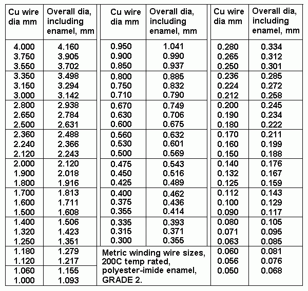
4. Choose wire size from Table 5 = 0.28mm Cu dia, oa dia = 0.334mm.

Table 5. Wire sizes for Grade 2 winding wire, 200C rated, polyester-imide
coating for industrial use.
table-wire-sizes.GIF


5. Calculate Pri RwP.
Turn average length TL = 2T + 2S + ( pye x H ) = 76mm + 102mm + 60mm = 238mm.
RwP = Np x TL / ( 44,000 x Cu dia squared ), where 44,000 is a constant.
RwP = 3,079t x 238mm / ( 44,000 x 0.28mm squared ) = 212r.

6. Calculate RwP losses.
RwP loss = 100% x RwP / ( RLa + RwP ) = 100% x 212r / ( 5,500r + 212r ) = 3.7%.

This may be as good as you might get.

7. Calculate Pri turns per layer and real Np.
Bobbin wind width, Bww = L - 4mm = 57mm - 4mm = 53mm.
Tpl = 0.97 x Bww / oa wire dia = 0.97 x 53.0mm / 0.334mm = 154tpl.

8. Calculated the number of Pri layers, and real Np.
No Layers = above Np / tpl = 3,079t / 154tpl = 19.99layers, so use 20 full layers  so
real Np = 20 x 154t = 3,080t.

9. Calculate height of bobbin contents expected so far :-
Maximum bobbin content = 0.8 x H for all OPT. This allows for wire bulge during winding
and a nominal 2.0mm bobbin base thickness plus clearance off iron core of 0.5mm 

All content height max = 0.8 x 19mm = 15.2mm.

Pri winding height = 20 layers x 0.334mm oa dia = 6.68mm.
Insulation area expected = 0.16 x 57mm x 19mm = 173sq.mm.
Expected insulation height = area / Bww = 173sq.mm / 53mm = 3.3mm.
Sec winding height may be 15.2mm - 6.68mm - 3.3mm = 5.22mm.

10. Choose interleaving pattern from within Tables 6,7,8,9.
From Table 6 :-
7W to 15W
10 to 20 2p~4p - S - 4p~8p - S - 4p~8p - S - 2p~4p 3S + 4P
OPT-5A can have 3 Pri layers of total 20 layers for CFB = 15%.
List possible sequence of winding layers and sections :-
3p-S-k-6p-S-k-5p-k-S-3p
"p" is a primary layer within an anode primary section.
"S" is 1 or more secondary layers within a secondary section.
"k" is a primary layer within a primary section, but for CFB.

Better might be

7W to 15W
10 to 20
S - 4p~6p - S - 4p~6p - S - 4p~6p - S
4S + 3P
List possible sequence of winding layers and sections :-
S-k-6p-S-k-5p-S-6p-k-S
.

11. Try to c
alculate Sec winding turns for OPT-5A for CFB, UL or triode.
Possible Sec wire winding height where all 3 Sec sections are 1 wire layer.
Calculate sec turns needed for 3 Sec loads between 3r3 minimum and 18r0 maximum.
OPT-5A wanted highest ZR for 5k5 : 3r3 = 1,666 : 1, TR = sq.rt ZR = 40.824.
Possible sec turns = Np / TR = 3,080t / 40.824 = 75.44, and omit fractions of a turn,
and use nearest number divisible by 2, ie, 76tpl.
76tpl gives 5k5 : 3.35r.
If 1/2 layers of 38t each are possible,
76t+38t = 114t for 7.54r, and 76t+76t = 152t = 13.4r.

12. Try to calculate Sec winding wire sizes. 
Possible Sec winding height from step 9 / No Sec layers = 5.22mm / 3 = 1.74mm.
Wire Table suggests 1.5mm Cu dia x 1.608mm oa dia, tpl = 53mm / 1.608mm = 32t,
and this gives 96t total, and not enough for 14r0 load match.
Try 76tpl. Possible wire size = 53mm / 76tpl = 0.697mm oa dia.
Wire table suggests 0.6mm Cu dia x 0.675mm oa dia is OK.
The available height per layer = 1.74mm, so 2 layers x 0.675mm = 1.35mm can be used
in each Sec section.
The total Sec turns = 6 x 76t = 456t.
This number 456 is exactly divisible by 2, 3, 4, 12.

Father Christmas has arrived for a special out-of-season gift to give such favourable
possible numbers.

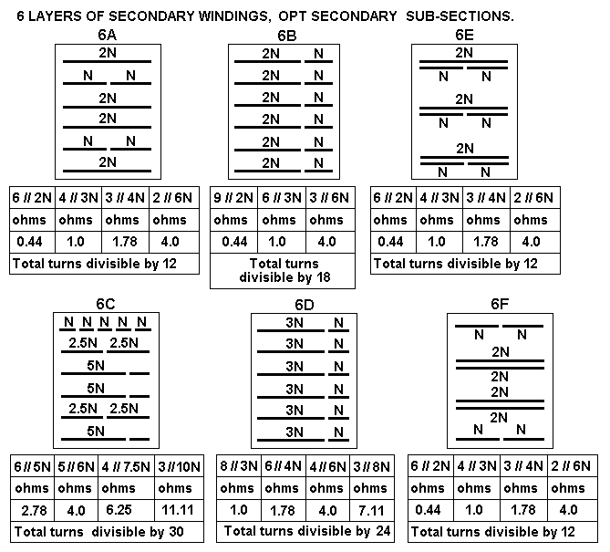
See Fig 12 below for 6 Sec layers and pattern 6F.
The first on and last on Sec layers can be 1 layer = 2 x 38t, and the two central double
layer sections 4 x 76t in 4 layers.
Because this is a small OPT, the primary may be 3 sections and still get excellent HF.
So possible windings are 6 // 76t for 3.35r, 4 // 78t+39t = 117t for 7.53r,
3 // 78t + 78t for 156t for 13.4r.

13. Calculate RwS for 4 // 114t for 7.5r = 114t x 238mm / ( 44,000 x 0.6mm x 0.6mm x 4 )
= 0.428r, RwS loss = 100% x 0.428r / ( 7.53r + 0.428r ) = 5.4%.

14. Calculate total RwP+S loss = 3.7% + 5.4% = 9.1%.

NOTE. Total Rw loss > 7%, but is it worth increasing size, weight and cost for 2% less
winding loss? Probably not, because I know youse hate paying for anything.

15. Heights of bobbin content so far :-
Primary 20 layers 0.334 = 6.68mm,
Secondary 6 layers 0.675mm  = 4.05mm,

Total allowed bobbin content height = 15.2mm,
Insulation height = 15.2mm - 6.68mm - 4.05mm = 4.47mm.

sequence of layers = S-k-6p-S-k-5p-S-6p-k-S.

Nomex 0.05mm between Pri layers at same Vdc = 14 layers = 0.7mm.
Height for thick insulation = 4.47mm - 0.7mm = 3.77mm.
There are 9 layers of thick insulation between Pri and Sec and pri to k.
There is one thick insulation layer over all windings,
Use 9 x 0.30mm, Cover 1 x 0.3mm.

16. Draw all details on one sheet for winding trades-person to wind :-
Fig 3. OPT-5A, 5k5 : 3r4, 7r5, 13r4.
OPT-5A-SE-12.7W-CFB-UL-5k5-3r4-7r5-13r4.GIF 

So what happens if lower Np is used?

Fig 4. OPT-5B, 5k5 :
OPT-5B-SE-12.7W-CFB-UL-5k5-3r3-7r4-16r7.GIF
OPT-5B has 17 layers of 0.28mm Cu dia primary and Fsat = 16.8Hz, and I show
simpler Secs with 4 layers of 1.0mm Cu wire, and you can see that if you allow
Fsat to increase +2.5Hz, the total Rw loss reduces from 9.1% to 6.6%.
OPT-5A or OPT-5B may sound identical.

If you allowed Fsat to be 24Hz, the Va could be 372Vrms giving 25.4W for 5k5.
But the Idc MUST increase from 68mAdc to 96mAdc. The air gap MUST increase to
allow effective µe to be lower, and so Lp will be lower and the XLp = 5k5 at 24Hz.

To get 372Vrms the peak Va = 526Vpk and Ea for a tube will be about +576Vdc and
this is well above sensible safe limits for most octal tubes, and Idle Pda = 55W.
So I cannot ever recommend OPT-5A or 5B be used for anything else other than
what the sheet details show.

For 12.7W with lower RLa loads, say 2,750r, the Va = 134Vrms = 187Vpk, idle Ia
= 90mAdc. Without any air gap change the Bdc will increase from 0.7T to 1.0T, but
Bac max is only 0.42T so total Bdc + Bac = 1.4T and the OPT works OK.
The Ea will be about +230Vdc, Idle Pda = 21W, which may suit 2 x EL84 in parallel.
But to get RLa = 2750r, you must connect sec loads that are 1/2 the shown valued in
sheet details say 3r5 where it should have 7r4, or 8r0 where it shows 16r7.
The winding resistance doubles from 6.6% to 13.2%, so in fact you may only get 12W
at Sec output.

One huge trouble with nearly all OPTs is that they all suit only one load value for
maximum Po, and low winding losses, and at all other loads the load matching
becomes sub-optimal, and the maximum Po is lower.

However, SE amps always work in class A and with loads that are double or half
the load for max Po, they can give excellent sound where the working Po max is less than
Po max available for the wrong load. For example, if output load = 3r5 where OPT is linked
for 7r4, and RLa = 2k7, max Po = 6W approx but if only 2W max is needed, sound is OK.

Fig 5. OPT-5C, Like previous 5A, 5B, but core = T44mm x S38mm.
OPT-5C-SE-12.6W-CFB-UL-5k0-3r3-7r5-16r8.GIF
Most will find they can get T38mm E+I more easily than T44mm.
NOTE. B+ of +450Vdc is the max anyone would probably use with triode and KT88, 6550.
For SEUL or CFB, the B+ would be lower. And cathode biasing will mean the Ea = B+ less Ek.
The tube type and its mode and Idle Pda must suit anode load of 5k0 + 7.8% winding loss
= 5k4 !!

Fig 6. OPT-5D, 10W for 5k0 : 3r5, 7r9, 14r1, and "small" E+I core.
OPT-5D-SE-10.0W-CFB-UL-5k0-3r4-7r7-13r7.GIF

Fig 7. OPT-5E, 22W for 2k5 : 3r9, 6r9, 15r4
OPT-5E-22W-CFB-UL-2k5-3r9-6r9-15r4.GIF
This can be used with 2 x KT88 in parallel. This will compete very favourably with
any other 22W tube amp including exotic amps with a single 845, 211, GM70, etc.
------------------------------------------------------------------------------------------------------------------
Tables 6, 7, 8, 9 show interleaving pattern possibilities for SE OPTs.
Table 6.
0W to 15W
Total P
layers
Primary and Secondary layer distribution.  
P+S
section
pattern
0 to 7W
10p to 24p
S - 10p~24p - S
2S + 1P
7W to 15W 10p to 20p S - 5p~10p - S - 5p~10p - S 3S + 2P
7W to 15W
10 to 20 2p~4p - S - 4p~8p - S - 4p~8p - S - 2p~4p 3S + 4P
7W to 15W
10 to 20
S - 4p~6p - S - 4p~6p - S - 4p~6p - S
4S + 3P

Table 7.
15W to
 30W
Total P
layers
Primary and Secondary layer distribution. P+S section
pattern

12p 2p - S - 4p - S - 4p - S - 2p 3S + 4P

12p S - 4p - S - 4p - S - 4p - S 4S + 3P

13p
2p - S - 3p - S - 3p - S - 3p - S - 2p 4S + 5P

14p 2p - S - 3p - S - 4p - S - 3p - S - 2p 3S + 4P

14p S - 5p - S - 4p - S - 5p - S 4S + 3P

15p
S - 5p - S - 5p - S - 5p - S 4S + 3P

16p 3p - S - 5p - S - 5p - S - 3p 3S + 4P

16p S - 4p - S - 4p - S - 4p - S - 4p - S 5S + 4P

16p 2p - S - 4p - S - 4p - S - 4p - S - 2p 4S + 5P

18p 3p - S - 6p - S - 6p - S - 3p 3S + 4P

18p S - 4p - S - 5p - S - 5p - S - 4p - S 5S + 4P

20p 3p - S - 7p - S - 7p - S - 3p 4S + 3P

20p S - 7p - S - 6p - S - 7p - S 5S + 4P

20p 2p - S - 5p - S - 6p - S - 5p - S - 2p 4S + 5P

22p
2p - S - 6p - S - 6p - S - 6p - S - 2p
4S + 5P

22p
S - 7p - S - 8p - S - 7p - S
4S + 3P

Table 8.
30W to
100W
Total P
layers
Primary and Secondary layer distribution. P+S section
pattern

13p
2p - S - 3p - S - 3p - S - 3p - S - 2p 4S + 5P

14 p S - 3p - S - 4p - S - 4p - S - 3p - S 5S + 4P

14p
2p - S - 3p - S - 4p - S - 3p - S - 2p 4S + 5P

15p
S - 5p - S - 5p - S - 5p - S 4S + 3P

15p
2p - S - 4p - S - 3p - S - 4p - S - 2p 4S + 5P

16p
S - 4p - S - 4p - S - 4p - S - 4p - S 5S + 4P

16p 2p - S - 4p - S - 4p - S - 4p - S - 2p 4S + 5P

18p S - 4p - S - 5p - S - 5p - S - 4p - S
5S + 4P

18p
2p - S - 5p - S - 4p - S - 5p - S - 2p 4S + 5P

19p
2p - S - 5p - S - 5p - S - 5p - S - 2p 4S + 5P

20 p S - 5p - S - 5p - S - 5p - S - 5p - S 5S + 4P

20p
2p - S - 5p - S - 6p - S - 5p - S - 2p 
4S + 5P

21p
3p - S - 5p - S - 5p - S - 5p - S - 3p 4S + 5P

22 p S - 5p - S - 6p - S - 6p - S - 5p - S
5S + 4P

22p
2p - S - 6p - S - 6p - S - 6p - S - 2p 4S + 5P

Table 9.
100W to
250W
Total P
layers
Primary and Secondary layer distribution. P+S section
pattern

10p 2p - S - 2p - S - 2p - S - 2p - S - 2p 4S + 5P

10p S - 2p - S - 3p - S - 3p - S - 2p - S 5S + 4P

10p 1p - S - 2p - S - 2p - S - 2p - S - 2p - S - 1p 5S + 6P

10p S - 2p - S - 2p - S - 2p - S - 2p - S - 2p - S 6S + 5P

12p 2p - S - 3p - S - 2p - S - 3p - S - 2p 4S + 5P

12p S - 3p - S - 3p - S - 3p - S - 3p - S 5S + 4P

12p 1p - S - 2p - S - 3p - S - 3p - S - 2p - S - 1p 5S + 6P

12p S - 2p - S - 3p - S - 2p - S - 3p - S - 2p - S 6S + 5P

12p
S - 2p - S - 2p - S - 4p - S - 2p - S - 2p - S 6S + 5P

13p
2p - S - 3p - S - 3p - S - 3p - S - 2p 4S + 5P

13p
S - 3p - S - 4p - S - 3p - S - 3p - S 5S + 4P

13p
S - 2p - S - 3p - S - 3p - S - 3p - S - 2p - S 6S + 5P

14p
2p - S - 3p - S - 4p - S - 3p - S - 2p 5S + 5P

14p S - 3p - S - 4p - S - 4p - S - 3p - S 5S + 4P

14p 1p - S - 3p - S - 3p - S - 3p - S - 3p - S - 1p 5S + 6P

14p S - 2p - S - 3p - S - 4p - S - 3p - S - 2p - S 6S + 5P

16p 2p - S - 4p - S - 4p - S - 4p - S - 2p
4S + 5P

16p S - 4p - S - 4p - S - 4p - S - 4p - S 5S + 4P

16p 2p - S - 3p - S - 3p - S - 3p - S - 3p - S - 2p 5S + 6P

16p S - 3p - S - 3p - S - 4p - S - 3p - S - 3p - S
6S + 5P

18p 2p - S - 5p - S - 4p - S - 5p - S - 2p
4S + 5P

18p S - 5p - S - 4p - S - 4p - S - 5p - S
5S + 4P

18p 2p - S - 4p - S - 3p - S - 3p - S - 4p - S - 2p 5S + 6P

18p S - 3p - S - 4p - S - 4p - S - 4p - S - 3p - S  6S + 5P

19p
S - 3p - S - 4p - S - 5p - S - 4p - S - 3p - S  6S + 5P

20p 3p - S - 5p - S - 4p - S - 5p - S - 3p 4S + 5P

20p S - 5p - S - 5p - S - 5p - S - 5p - S 5S + 4P

20p 2p - S - 4p - S - 4p - S - 4p - S - 4p - S - 2p 5S + 6P

20p S - 4p - S - 4p - S - 4p - S - 4p - S - 4p - S
6S + 5P

21p
S - 4p - S - 4p - S - 5p - S - 4p - S - 4p - S 6S + 5P

21p
3p - S - 5p - S - 4p - S - 5p - S - 3p 4S + 5P

22p 3p - S - 5p - S - 6p - S - 5p - S - 3p 4S + 5P

22p S - 5p - S - 6p - S - 6p - S - 5p - S 5S + 4P

22p 2p - S - 5p - S - 4p - S - 4p - S - 5p - S - 2p
5S + 6P

22p S - 4p - S - 6p - S - 4p - S - 6p - S - 4p - S 
6S + 5P

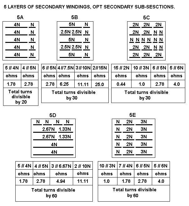
Fig 8,9,10,11,12 for OPT secondary windings sub-divided for many load matches :-
Fig 8.
opt-sec-2ABC-sub-sections.GIF

Fig 9.
opt-sec-3ABC-sub-sections.GIF

Fig 10.
opt-sec-4ABC-sub-sections.GIF

Fig 11.
opt-sec-5ABCDE-sub-sections.GIF

Fig 12.
opt-sec-6ABCDEF-sub-sections.gif

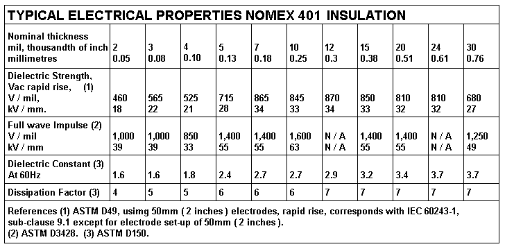
Table 10. Nomex 401 properties.
Re-typed-nomex-401-ratings-table.GIF
Table 10 replaces a previous table based on more simple reasons before I became fully aware
of properties of Nomex 401.
Do Not Use Kraft Paper of any other insulation with high Dielectric Constant.
I do not recommend use of Teflon insulation because varnish will not adhere to it, and it is a difficult
slippery material to use, disgustingly expensive, and usually unavailable in small quantities and it does
not have a significantly lower dielectric constant to justify its use to reduce shunt capacitance and
increase bandwidth.

If CFB is not used, all anode p layers and cathode k layers form one winding at up to +450Vdc, for
SEUL, or triode.

For calculations of properties of these OPTs and for OPT- 4 for 35W, proceed to :-

SE OPT calc Page 2

SE OPT calc Page 3