SE OPT CALCULATIONS PAGE 2.
Design OPT-4A for 35W output from 4 x EL34 parallel SE for CFB or UL.
Steps 1 to 20.
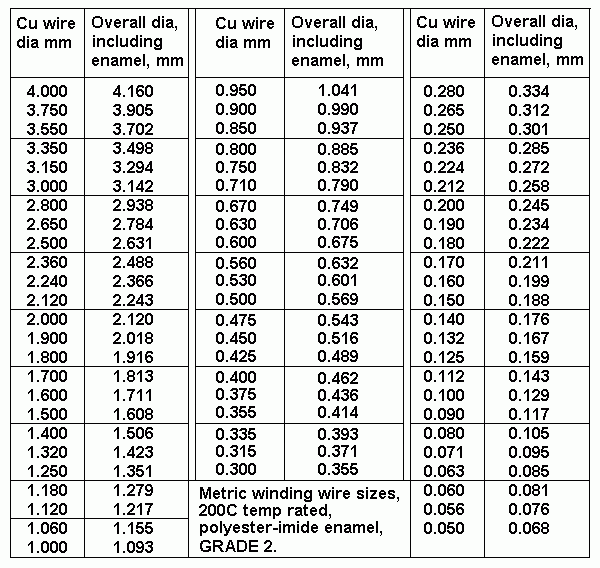
Table 1. Wire sizes for Grade 2 magnetic winding wire, polyester-imide coated.
Table 2,3,4,5 for most possible and useful interleaving patterns.
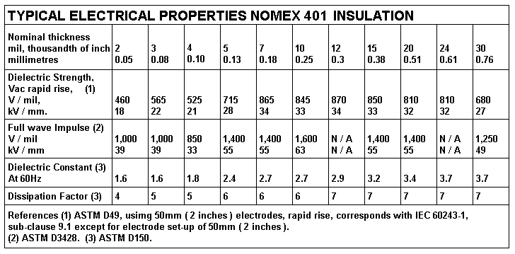
Table 6. Nomex 401 insulation sizes and properties.
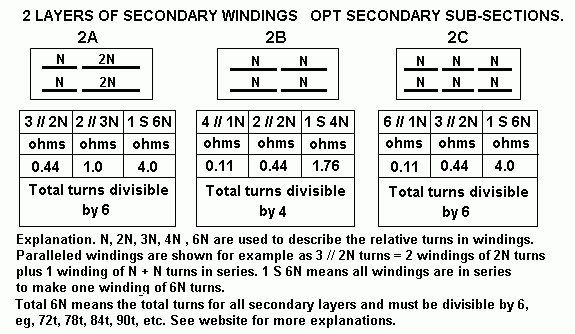
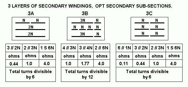
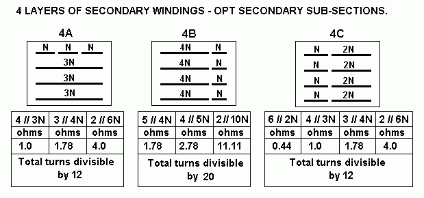
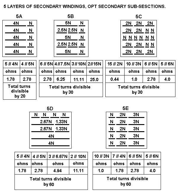
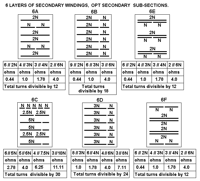
Fig 1 to 6 for Secondary section subdivisions to obtain many load matches.
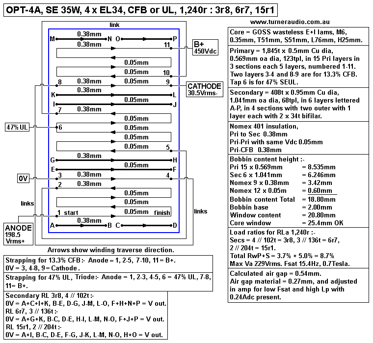
Fig 7, OPT-4A, T51mm x S51mm core, SE 35W, CFB or SEUL.
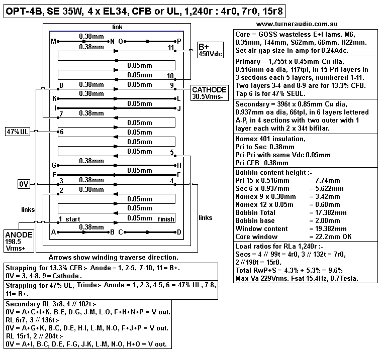
Fig 8, OPT-4B, T44mm x S62mm core, SE 35W, CFB or SEUL.
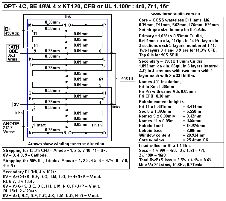
Fig 9, OPT-4C, T51mm x S62mm core, SE 49W, CFB or SEUL.
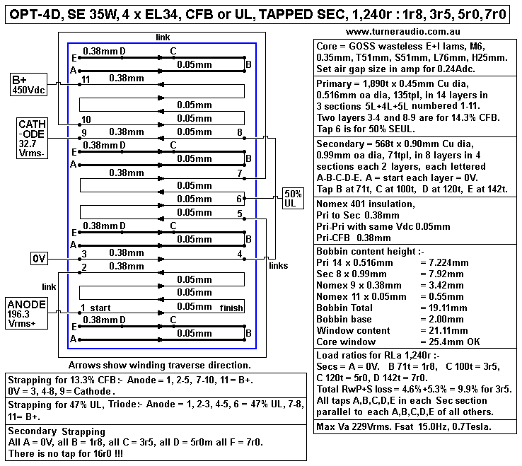
Fig 10. OPT-4D, T51mm x T51mm core, SE 35W, TAPPED SECONDARY.
Notes for tapped Sec windings and trifilar winding.
Calculation of SE OPT-4A properties, LL, Csh, Lp etc.
Steps 1 to 9.
Table 7. Capacitance in OPT-4A.
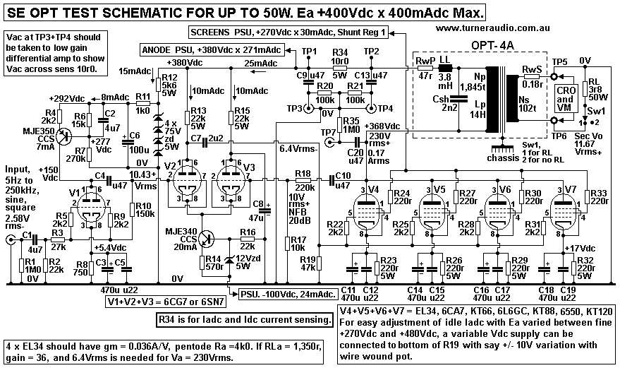
Fig 11. Schematic for tube amp to test OPT with LCR model for OPT-4A.
How the amp works.
Using amp to test and measure OPT-4A
A. Measure Pri Vac : Sec Vac with no Sec load at 1kHz to check TR.
B. Measure max Po at Sec with Sec load, and anode power into Pri.
C. Measure unloaded Pri input impedance, Pri Zin, measure Lp, Csh, and resonant
Fo for Csh // Lp, and series Csh + LL.
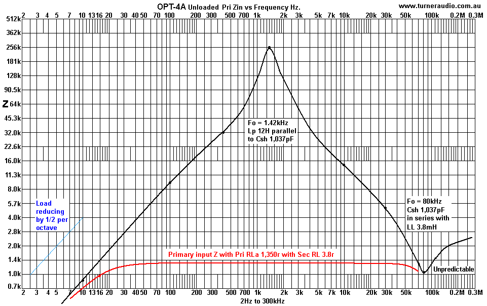
Graph 1. OPT-4A Pri Zin vs F non loaded and loaded.D. Measure Fsat at LF.
E. Set the air gap to best size. Measure LL, and confirm RwP+S at Primary.
Table 8. Shows effects of air gap change for OPT-4A.
F. Measure OPT-4A leakage inductance LL and RwP+S at Pri.

Notes on measuring a newly wound OPT.....
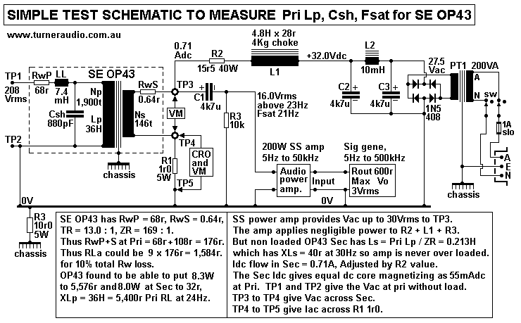
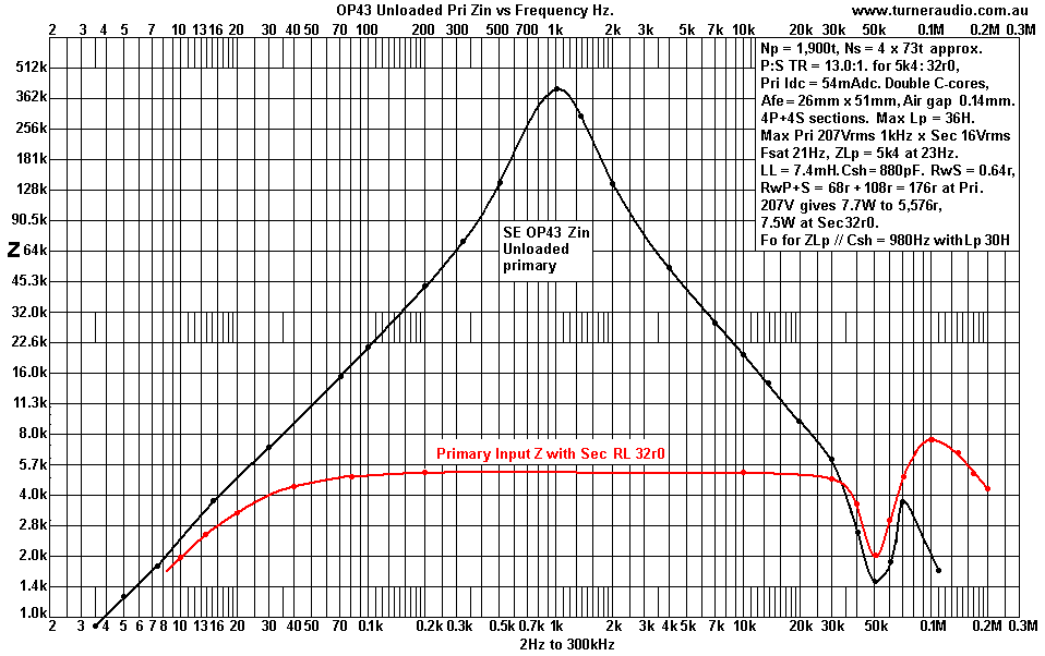
Find out the properties of an unknown quality SE OP43.
Fig 12. Test schematic for OP43 or others.

Graph 2. OP43 Pri input Z vs F.

To measure the total RwP+S and the LL, a different test set is easiest.

Notes on :-
Any unknown quality SE OPT can be measured,
Vac meters,
Oscilloscopes,

Conclusions about OPT-4D with Tapped Secondary windings.
Where to buy E+I lams in Australia.
Re-using E+I laminations from old fused power transformers.
The iron behavior in PP and SE cores.
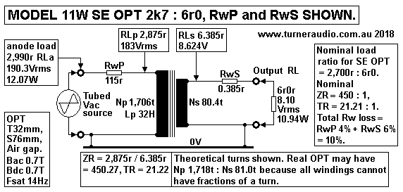
Table 9. Relative core sizes to anode Po assuming RwP loss = 4%, RwS loss = 6%, Fsat 14Hz.
How did I get Table 9 figures?
Fig 13. Simple Model of SE OPT showing perfect model transformer with added RwP and RwS.
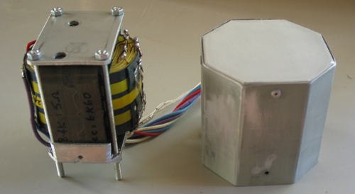
Potting OPT.
Fig 14. picture of OPT and its pot before potting it
Blank Graph sheet for plotting Vo Versus F for amp F response or Z vs F for impedance.
--------------------------------------------------------------------------------------------------------------------------------
Design SE OPT-4A for 35W for 4 x EL34 parallel pentodes in SE mode with CFB similar to
OPT for se35cfb-monobloc.html
At this page, measured Va-k = 228Vrms.
Confirm Idle conditions for 4 x EL34 in parallel :-
Ea = ( B+ +380Vdc ) - ( Ek +18.5Vdc ) - ( Vdc across anode portion OPT Pri 8Vdc )
= +353.5Vdc.
Ia = 4 x 60mAdc = 240mAdc, Pda = 84.8W. Pda for each EL34 = 21.2W.
Eg2 = ( B+ +280Vdc ) - ( Ek +18.5Vdc ) - ( Vdc across 220r +1.7Vdc ) = +259.8Vdc.
Ig2 = 30mAdc, Pdg2 = 7.8W.
Total Pda+g2 = 92.6W = 23.15W for each EL34, and this is 5W less than max rating for Pda+g2.

The OPT I made For SE35W has :-
GOSS Wasteless E+I lams, T44mm x S62mm, L66mm x H22mm. I recorded air gap = 0.87mm
using 0.43mm air gap material across the whole 132mm x 62mm area between E and I, because
there are two gaps in the ML path around each winding window.

Interleaving pattern is basically 4Sec x 3Pri sections. Primary has 16 layers at 122tpl of 0.45mm
Cu dia wire, 0.516mm oa dia, with 3 anode winding sections of 5 layers, 4 layers, and 5 layers.
These are wound between 4 Sec sections with a total of 6 layers of 62tpl of 0.9mm Cu dia wire.
The 4 Sec sections are :-
Section 1 = 1 layer of 2 x 31t,
Sections 2 and 3 = 2 layers of 62t each,
Section 4 = 2 layer of 2 x 31t.

Between the two layers of Sec sections 2 and 3, there is one layer of primary winding devoted to
12.5% of local cathode feedback in the output stage.
So the wire layer build up in bobbin can be described :-
S-p-p-p-p-p-S-k-S-p-p-p-p-S-k-S-p-p-p-p-p-S.

"S" = Sec layer, "p" = primary layer in anode circuit, "k" = primary layer in cathode circuit.
0.4mm polyester insulation is between all S to p interfaces, and 0.05mm between p to p layers
and also between S to k interfaces. The placement of CFB windings between sec layers was an
experiment which worked well, but no better than where I more commonly placed CFB layers
between grouped anode layers a Sec layers and with the same 0.4mm insulation.

Total RwP+S = 10.3% of anode load.
Rwp is 4.5% of total Rw, RwS is 5.8% of total Rw.
RwP for 16 layers of anode and cathode windings = 62r.
Where OPT is strapped for 1,952t : 3 // 124t for nominal 1,239r : 5r0 loading, the Sec RwS
= 0.326r, which appears at primary as ZR x RwS = 247.8 x 0.326r = 81r, so total RwP+S at
primary = 62r + 81r = 143r, and the total anode load = nominal 1,239r + 143r = 1,382r.
Total winding loss = 100% x 143r / 1,382 = 10.3%.

So where there is 35W at output at Sec, the tubes
make 38.5W to primary, and 3.5W is lost as heat in the winding resistance.

Total of nominal RLa + RwP+S = 1,240r + 143r = 1,383r.
Anode power to 1,383r is 38.5W, and output power to 5r0 at Sec = 35W.

Each EL34 operates with total load = 4 x 1,382r = 5,528r. Equivalent RwP+S for each EL34
= 4 x 143r = 572r, so OPT primary load for each EL34 = 5,528r - 572r = 4,956r.
The RLa for design for max Po = 5,528r,

Design Steps OPT-4A :-
1. Determine RLa for 38W at anodes from 4 x EL34.
In se-output-trans-calc-1.html, 1/3 way down page, Fig 2 shows 5 loadlines for RLa for
one EL34 that can be one of 4 parallel EL34 for SE35cfb.
The amp schematic is SHEET 1 - 2011, at that page, and operation is explained.
The principles for use of 1 x EL34 can be applied for the use of any number of of parallel EL34.

For 4 x EL34, idle Pda = 4 x 21.25W = 85.0W and max Po at anode connection of OPT
= 0.45 x 85W = 38.25W. If total winding loss = 10.0%, expect 34.8W at Sec output.
For 10% total Rw loss, RLa = RwP +[ ZR x ( Sec RL + RwS ).
More simply, if you have Pri load without Rw = ZR x Sec RL = 1,240r,
and total RwP+S loss = 10%, then total RwP+S measured at Pri = ZR x Sec RL / 9.0.
For OPT-4A, RLa = 1,240r + 138r = 1,377r.
For 38.25W to 1,377r, Va = sq.rt ( 38.25W x 1,377r ) = 229.5Vrms.

NOTE. Pure class A anode efficiency cannot ever exceed 50%, and for pentode or tetrode
operation it can be up to 47% measured at anode, providing THD < 1%, only possible with
enough NFB and or other THD reduction methods for SE amps. The OPT winding losses
reduce the overall efficiency maximum to about 41% if all things are optimised. The idle Pda
does not the screen Pdg2 or heater power which would then reduce efficiency to 35%.

But efficiency cannot be heard; it does not cause cause any sonic blemish. At at average
listening levels of say 3W, efficiency is truly terrible, and I suggest you put an extra solar panel
on your roof and a battery so your conscience is not bothered by you causing greenhouse
warming.

The OPT design used for my SE35cfb amp does not have to be exactly copied, and I explain
design procedure for something equal or better :-

2. Calculate theoretical Afe for maximum 38W at anode. ThAfe = 450 x sq.rt Po in sq.mm
= 450 x 6.16 = 2,773sq.mm.
This formula is only true for AFe section with Tmm = Smm, total RwP+S < 10%, Fsat < 20Hz,
and still have enough room in bobbin winding window for enough interleaved P+S sections plus
insulation for HF cut off > 50kHz for max Po level at 1kHz.

Table 8 below gives a huge list of core sizes to ensure RwP+S loss < 10%, with RwP loss = 4%,
RwS loss 6%, and Fsat = 14Hz.

3. Calculate T, S, L, H core dimensions for GOSS wasteless pattern E+I laminations.
For a square core centre leg section, T = S and for Afe = 2,773sq.mm, T = 52.7mm.
52.7mm is NOT a standard manufactured size so you must choose from what is available :-

Wasteless E+I lamination T sizes are 25.4mm, 31.75mm, 38.1mm, 44.45mm, 50.8mm, 63.5mm.
These metric sizes correspond to imperial inch sizes of 1", 1.25", 1.75", 2.0", 2.5".
NOTE. European wasteless T sizes are different so you may need total design revision if you use
T40mm Euro size where design calls for T38mm.

If T = S = 52.7mm, theoretical core volume = 6 x T cubed = 878cc. ( T is in centimetres ).
Core weight in Kg = Core Volume x Si-Fe density = 878cc x 7.6gm per cc ) / 1,000 = 6.7Kg.
Now the nearest Tmm size made to theoretical 52.7mm is 50.8mm so this is what will be used.

S should be more than 52.7mm to give Afe = equal or more than theoretical 2,773sq.mm.
The theoretical core volume can remain at 878cc.
Volume = 6 x T squared x S, so
S = Volume / ( 6 x T squared ) = 878cc / 6 x 5.08cm squared ) = 5.67cm = 57mm.
But this does not suit the range of available plastic moulded bobbins which my be for :-
T51mm x S51mm, T51mm x 63mm, T51mm x S76mm.
You could reduce a S63mm to be S57, but easiest solution is to try bobbin T51mm x S51mm,
and see if you really need to have S57mm or S63mm,

In the SE35 amps I made, I used T44mm x S63mm for Afe = 2,772sq.mm, close to theoretical
needed 2,777sq.mm. Total Rw was above 10%.
if you have 51mm x 51mm for Afe = 2,601sq.mm, the bigger winding window may allow more
turns and thicker wire.
Try T51mm x S51mm for Afe = 2,601sq.mm.

4. Calculate theoretical Np.
Max Bac + Bdc for GOSS E+I should not exceed 1.4Tesla. Bac and Bdc should each = 0.7T.
For Bac = 0.7T, Fsat 14Hz, Np = Vac x 226,000 / ( Afe x F x B )
= 229Vrms x 226,000 / ( 2,601sq.mm x 14Hz x 0.7Tesla ) = 2,030 turns.

5. Calculate theoretical wire size.
Pri wire occupies area approx 0.28 x L x H = 0.28 x 25.4mm x 76mm = 540sq.mm.
Wire size oa dia = sq.rt ( area occupied by Pri / Np ) = sq.rt ( 540 / 2,030t ) = 0.515mm.
Wire table below suggests 0.45mm Cu dia x 0.516mm oa dia.

6. Calculate theoretical RwP.
Calculate average turn length TL for square core = 5.57 x T = 5.57 x 51mm 284mm.
thRwP = Np x TL / ( 44,000 x Cu dia squared )
= 2,030 x 284mm / ( 44,000 x 0.45 squared ) = 65r.
RwP loss = 100% x RwP / ( RLa + RwP ) = 100% x 65r / 1,240r + 65r ) = 4.98%.
However, if the Sec RwS is also 5%, then at primary input the load = 1,240r + 5% = 1,302r,
so loss due RwP = 100% x ( 65r / 1,302r + 65r ) = 4.75%. The maths don't show much
difference but so far, RwP loss > 5% = OK.

Conclusion 1. Pri loss % is ideally < 4%, and Sec should be < 6%, for total Rw loss < 10%,
The heat in 65r = 3.8W, OK for the size of the OPT.

Conclusion 2. For a smaller T, the window area is reduced and you cannot ever fit
th2,033 turns of 0.45mm Cu wire and still have enough room for the Sec.

Conclusion 3. For a smaller T, the S must be more than T, and be enough to increase
Afe to reduce Np for same Fsat so that the lower Np will fit in to smaller window without
increasing Rw losses.

Conclusion 4. For smaller T = 44mm, and and for total 10% Rw loss and Fsat 14Hz,
core S = 878cc / ( 6 x 4.4 squared ) = 7.55cm = 76mm, so in theory the is S44 x T76mm,
Afe = 3,344sq.mm, Np becomes 1,547t and Rw = 53r, for loss = 3.7%.
Core weight is same.
Where Afe and window size are both slightly too small than theory demands, perhaps Fsat
can be allowed to be 17Hz, so Np and Ns are lower and total RwP+S < 10%.
Someone with better mathematical brain cells than myself would have a better formula
to prevent the trial and error design system used here. Now all any maths wizard has to
do is be able to code a program to consider 6 different core possibilities and chose the
best, in a kind of human manner. The AI available in 2018 is unable to design a good OPT
or control a robot to wind it, or tie my shoe laces, or to read my .gif schematics or read my
website or winding diagrams where everything needed for an OPT is shown. Maybe thing
will get better bu 2038, but by then, watch out, Big Robot issa comin afta youse.

For OPT-4A, T51mm x S51 and Afe = 2,601sq.mm may be OK, and there are standard
bobbins to suit. Core Volume = 787cc.
Weight = 787cc x 7.6 / 1,000 = 5.97Kg, about 10% less than ideal core volume and weight.
Fsat of 14Hz may be possible, total winding loss may be < 10%
less than 10%.

To get RwP lower, Try Fsat = 16Hz, with lower and with larger wire size.

ThNp = 229V x 226,000 / ( 2,601 x 16Hz x 0.7T ) = 1,776t.
Oa dia wire = sq.rt ( 540sq.mm / 1,776t ) = 0.551mm, so try wire size 0.5mm Cu dia
and 0.569mm oa dia.
Theoretical RwP = 1,776t x 284mm / ( 44,000 x 0.5mm squared ) = 46r.
RwP loss = 46r / ( 1,240r + 65r Rws + 46r ) = 3.4%, and better.

7. Calculate Pri wire size and layers, and revised Np.
oa dia = 0.569mm.
Bobbin winding width Bww = 76mm - ( 2 x 2mm cheeks ) = 72mm.
Ntpl = 0.97 x Bww / oa dia = 0.97 x 72mm / 0.569mm = 123tpl.

Theoretical No of layers = 1,776t / 123tpl = 14.44. Try 15.0 full layers.
 
Revised Np = 15 x 123t = 1,845t which reduces Fsat to 15.4Hz OK.
Final Real RwP = 48r.

Table 1. Grade 2 winding wire sizes.
table-wire-sizes.GIF
9. Calculate Idc density of Pri wire at idle condition. It should not exceed 2A / sq.mm.
0.50mm Cu dia wire has area = 0.196sq.mm. Idle Ia dc = 240mA, so Iadc density =
0.240A / 0.196sq.mm = 1.22A / sq.mm = OK.

10. Calculate Pri idle heat = RwP x Idc squared = 48r x 0.242Asquared = 2.8W.
The T rise will be very low for an OPT with such high surface area.
But bias failure of one of more output tubes could cause much higher Idc and wire could
overheat so you MUST use an active protection circuit in amp.

11. Choose interleaving pattern for high frequency cut off > 70kHz, -3dB, when amp is loaded
with RLa for maximum Po and correct secondary resistance load. See below Tables 2 to 5
for choice for OPT-4.

Table 2. Interleaving patterns.
0W to
15W
Total P
layers
Primary and Secondary
layer distribution.
P+S
section pattern
0 to 7W
10p to 24p
S - 10p~24p - S
2S + 1P
7W - 15W 10p to 20p S - 5p~10p - S - 5p~10p - S 3S + 2P
7W - 15W
10 to 20 2p~4p - S - 4p~8p - S - 4p~8p - S - 2p~4p 3S + 4P
7W - 15W
10 to 20
S - 4p~6p - S - 4p~6p - S - 4p~6p - S
4S + 3P

Table 3. Interleaving patterns.
15W
to 30W
Total P
layers
Primary and Secondary
layer distribution.
P+S
section pattern

12p 2p - S - 4p - S - 4p - S - 2p 3S + 4P

12p S - 4p - S - 4p - S - 4p - S 4S + 3P

13p
2p - S - 3p - S - 3p - S - 3p - S - 2p 4S + 5P

14p 2p - S - 3p - S - 4p - S - 3p - S - 2p 3S + 4P

14p S - 5p - S - 4p - S - 5p - S 4S + 3P

15p
S - 5p - S - 5p - S - 5p - S 4S + 3P

15p
2p - S - 4p - S - 3p - S - 4p - S - 2p
4S + 5P

16p 3p - S - 5p - S - 5p - S - 3p 3S + 4P

16p S - 4p - S - 4p - S - 4p - S - 4p - S 5S + 4P

16p 2p - S - 4p - S - 4p - S - 4p - S - 2p 4S + 5P

18p 3p - S - 6p - S - 6p - S - 3p 3S + 4P

18p S - 4p - S - 5p - S - 5p - S - 4p - S 5S + 4P

20p 3p - S - 7p - S - 7p - S - 3p 4S + 3P

20p S - 5p - S - 5p - S - 5p - S - 5p - S 5S + 4P

20p 2p - S - 5p - S - 6p - S - 5p - S - 2p 4S + 5P

Table 4. Interleaving patterns.
30W to
100W
Total P
layers
Primary and Secondary
layer distribution.
P+S
section pattern

11p
S - 4p - S - 5p - S - 4p - S
4S + 3P

11p
2p - S - 2p - S - 3p - S -2p - S - 2p
4S + 5P

12p
S - 4p - S - 4p - S - 4p - S 4S + 3P

12p
2p - S - 3p - S - 2p - S - 3p - S - 2p
4S + 5P

13p
S - 4p - S - 5p - S - 4p - S 4S + 3P

13p
2p - S - 3p - S - 3p - S - 3p - S - 2p 4S + 5P

14p
S - 5p - S - 4p - S - 5p - S
4S + 3P

14p S - 3p - S - 4p - S - 4p - S - 3p - S 5S + 4P

14p
2p - S - 3p - S - 4p - S - 3p - S - 2p 4S + 5P

15p
S - 5p - S - 5p - S - 5p - S 4S + 3P

15p
2p - S - 4p - S - 3p - S - 4p - S - 2p 4S + 5P

16p
S - 5p - S - 6p - S - 5p - S
4S + 3P

16p
S - 4p - S - 4p - S - 4p - S - 4p - S 5S + 4P

16p 2p - S - 4p - S - 4p - S - 4p - S - 2p 4S + 5P

18p S - 4p - S - 5p - S - 5p - S - 4p - S
5S + 4P

18p
2p - S - 5p - S - 4p - S - 5p - S - 2p 4S + 5P

19p
2p - S - 5p - S - 5p - S - 5p - S - 2p 4S + 5P

20 p S - 5p - S - 5p - S - 5p - S - 5p - S 5S + 4P

20p
2p - S - 5p - S - 6p - S - 5p - S - 2p 
4S + 5P

21p
3p - S - 5p - S - 5p - S - 5p - S - 3p 4S + 5P

22 p S - 5p - S - 6p - S - 6p - S - 5p - S
5S + 4P

22p
2p - S - 6p - S - 6p - S - 6p - S - 2p 4S + 5P

Table 5. Interleaving patterns.
100W
to 250W
Total P
layers
Primary and Secondary
layer distribution.
P&S
section pattern

10p 2p - S - 2p - S - 2p - S - 2p - S - 2p 4S + 5P

10p S - 2p - S - 3p - S - 3p - S - 2p - S 5S + 4P

10p 1p - S - 2p - S - 2p - S - 2p - S - 2p - S - 1p 5S + 6P

10p S - 2p - S - 2p - S - 2p - S - 2p - S - 2p - S 6S + 5P

12p 2p - S - 3p - S - 2p - S - 3p - S - 2p 4S + 5P

12p S - 3p - S - 3p - S - 3p - S - 3p - S 5S + 4P

12p 1p - S - 2p - S - 3p - S - 3p - S - 2p - S - 1p 5S + 6P

12p S - 2p - S - 3p - S - 2p - S - 3p - S - 2p - S 6S + 5P

12p
S - 2p - S - 2p - S - 4p - S - 2p - S - 2p - S 6S + 5P

13p
2p - S - 3p - S - 3p - S - 3p - S - 2p 4S + 5P

13p
S - 3p - S - 4p - S - 3p - S - 3p - S 5S + 4P

13p
S - 2p - S - 3p - S - 3p - S - 3p - S - 2p - S 6S + 5P

14p
2p - S - 3p - S - 4p - S - 3p - S - 2p 5S + 5P

14p S - 3p - S - 4p - S - 4p - S - 3p - S 5S + 4P

14p 1p - S - 3p - S - 3p - S - 3p - S - 3p - S - 1p 5S + 6P

14p S - 2p - S - 3p - S - 4p - S - 3p - S - 2p - S 6S + 5P

16p 2p - S - 4p - S - 4p - S - 4p - S - 2p
4S + 5P

16p S - 4p - S - 4p - S - 4p - S - 4p - S 5S + 4P

16p 2p - S - 3p - S - 3p - S - 3p - S - 3p - S - 2p 5S + 6P

16p S - 3p - S - 3p - S - 4p - S - 3p - S - 3p - S
6S + 5P

18p 2p - S - 5p - S - 4p - S - 5p - S - 2p
4S + 5P

18p S - 5p - S - 4p - S - 4p - S - 5p - S
5S + 4P

18p 2p - S - 4p - S - 3p - S - 3p - S - 4p - S - 2p 5S + 6P

18p S - 3p - S - 4p - S - 4p - S - 4p - S - 3p - S  6S + 5P

19p
S - 3p - S - 4p - S - 5p - S - 4p - S - 3p - S  6S + 5P

20p 3p - S - 5p - S - 4p - S - 5p - S - 3p 4S + 5P

20p S - 5p - S - 5p - S - 5p - S - 5p - S 5S + 4P

20p 2p - S - 4p - S - 4p - S - 4p - S - 4p - S - 2p 5S + 6P

20p S - 4p - S - 4p - S - 4p - S - 4p - S - 4p - S
6S + 5P

21p
S - 4p - S - 4p - S - 5p - S - 4p - S - 4p - S 6S + 5P

21p
3p - S - 5p - S - 4p - S - 5p - S - 3p 4S + 5P

22p 3p - S - 5p - S - 6p - S - 5p - S - 3p 4S + 5P

22p S - 5p - S - 6p - S - 6p - S - 5p - S 5S + 4P

22p 2p - S - 5p - S - 4p - S - 4p - S - 5p - S - 2p
5S + 6P

22p S - 4p - S - 6p - S - 4p - S - 6p - S - 4p - S
6S + 5P

11 continued.....
Choose 4S+3P interleaving pattern for 15 Pri layers from above Table 4 :-

35W 15p
S - 5p - S - 5p - S - 5p - S 4S + 3P

"5p" means 5 layers of primary wire in one Pri section.
Each P section has equal layers of wire, so there is no need to worry about imperfect magnetic symmetry.
There will be a minimum of unwanted HF resonances.

12. Nominate Pri layers for CFB between 12% and 20% of total primary layers. There are 15 Pri layers,
so 2 x CFB layers give 13.3% CFB = enough, and 3 x CFB layers give 20% CFB.

In this case, use 2 x Pri layers for CFB, using the 2 outer most Pri layers. Nominate the layer sequence :-
= S - k - 4p - S - 5p - S - 4p - k - S. Each "k" is a CFB layer.

The two k layers and all S layers are at near 0Vdc, but all 12 other p layers may be at B+ = +380Vdc.

13. Nominate insulation used. Use 0.38mm Nomex between all S and other p or k layers, and
between k layers and p layers.
use 0.05mm Nomex between p layers at same Vdc. This gives good insulation and low capacitances.
Use 0.38mm to cover all windings when winding is complete. 

Table 6. Voltage vs Insulation thickness between layers of grade 2 winding wire.
Re-typed-nomex-401-ratings-table.GIF
For OPT-4, anode primaries may be at up to +450Vdc, with secondaries and CFB
primaries at 0V. Use 0.38mm between any interface with high Vdc difference, and 0.05mm
between primary layers with same Vdc.

14. List height of the bobbin contents so far...
Primary = 15 x 0.569mm = 8.535mm
0.38mm insulation between P-S, 6 x 0.38mm = 2.28mm.
0.38mm insulation between P-CFB, 2 x 0.38mm = 0.76mm
0.38mm cover over last primary, 1 x 0.4mm = 0.38mm
0.05mm insulation between P-P, 10 x 0.05mm = 0.50mm.
Sub total = 12.455mm.

Total available height in bobbin = 0.8 x H = 0.8 x 25mm = 20.0mm
Maximum height of 4 x Sec winding layers = 20.0mm - 12.455mm = 7.545mm.

15. Calculate theoretical Sec wire size and Sec turns.
Option A. There may be 4 Sec sections of equal height = 7.545mm / 4 = 1.886mm each.
Each Section may have 1 layer 1.70mm Cu x 1.813mm oa dia for 39t max.
Each Section may have 2 layers 0.80mm Cu dia x 0.885mm oa dia for 81t max, with 0.05mm
insulation between. There are a total of 4 layers OR 8 layers of wire.

Option B. There may be 4 sections, with outer two with max height = 1.241mm each for one
layer wire only. The inner two sections have max height = 2.483mm each for 2 layers of the
same wire. Inner Sections may have 2 layers 1.12mm Cu dia x 1.217mm oa dia = 59t max,
with 0.05mm insulation between. Outer Sections may have 1 layer 1.12mm Cu dia x 1.217mm
oa dia = 59t max. There is a total of 6 layers of wire.

With all options, you cannot use wire that is above the sizes shown, but you may have up to
10% less tpl for max size. You can use smaller wire dia and have more turns tpl.

NOTE. Do not try to use 5S+4P or 6S+5P interleaving because shunt capacitance increases
and more bobbin winding area is occupied by the increased number of insulation layers.
If you insist on more interleaving, the core stack must be increased, so Np can be reduced using
same Pri wire size so less Pri layers are needed, and there is more room for insulation layers
which have to be thicker for increased layers to keep shunt C low. There is no point in reducing
LL to extremely low levels while increasing shunt C.  

16. Calculate possible Pri to Sec load matches with Np = 1,845t. RLa = 1,240r.
Note that RLa does not include any RwP or RwS which makes the calculations far too complex.
For calculation of load matches, ignore all RwP or RwS.
 
OPT Sec load matches should be slightly lower than the nominal speaker loads of 4r0, 8r0,
or 16r0 to cope with low minimum loads of speakers, so that the OPT may give 1,240r : 3r3
so speaker min Z of say 2r8 is better handled. The max speaker Z might be 20r, but this may
be where the speaker has high sensitivity so it makes the same SPL for same Vo for 2r8.

Three load matches are wanted between 3.3 and 16r. With Np = 1,845t for 1,240r Pri load,
98t Sec = 3.5r, 139t = 7.04r, 196t = 14.0r.
Many people with poor ability for pattern recognition will struggle to find the best wire size and
secondary subdivision pattern to achieve :-
1. The available bobbin height for all Sec windings is nearly filled.
2. There are 3 load matches, between 3.3r and 16.0r.
3. Current density in each Sec wire is equal,
4. There are no wasted or unused Sec turns for each linking pattern for each load match,
5. Leakage inductance is the same for all load matches,
6. Transformed RwS at Pri remains equal.

Option A with 4 Sec sections, each 1 layer.
See Fig 3 below, pattern 4A, but without any need to sub-divide any single layer,
and total Sec turns are exactly divisible by 4.
With Sec = 4 x 39tpl windings, available ways to arrange windings are :-
4 // 39t, Ns 39t = 0.55r.
2 // ( 39t+39t ), Ns 78t = 2.22r.
39t + ( 2 // 39t ) + 39t, Ns 117t = 4.98r.
4 x 39t all in series, Ns 156t = 8.86r.
For only 117t, current density is not equal so the RwS is highest for this link pattern.
Rw for 39t x 1.7mm Cu dia = 0.0871t. For Ns 117t, RwS = 0.0871r + 0.436r + 0.0871r
= 0.217r, and for a 5r0 load the RwS loss = 4.16%, and quite acceptable.
But only Ns 117t is useful for 5.0r is OK for all speakers > 5r0. With a 4r0 speaker with
min Z = 2r8, performance is not good.

The tpl could be increased to 48tpl so all 4 layers in series gives 192t for 13.43r.
Wire size = 1.32mm Cu dia x 1.423mm oa dia. The 48t easily fits into Bww 72mm, and turns
should be slightly spread apart evenly.
2 // ( 48t+48t ), Ns 96t = 3.36r.
48t + ( 2 // 48t ) + 48t, Ns 144t = 7.55r.
4 x 48t all in series, Ns 192t = 13.44r. This gives 3 useful loads, and may be the
simplest solution.

RwS for 144t and 7.55r = 0.444r, so RwS loss = 100% x 0.444r / 7.994r = 5.5%.
The OPT TR = 1,845t : 144t = 12.8125 : 1, ZR = 164.16 : 1.
Therefore Rws appears in series with Pri and = ZR x RwS = 164.16 x 0.444r = 79r.
The total PwP+S at Pri input = 48r + 79r = 127r.
The Ea+Idc idle conditions for max Po require RLa = 1,383r, and if Rw = 127r, the OPT
Pri RL = 1,383r - 127r = 1,256r, and the Sec load must be Pri RL / ZR
= 1,256r / 164.16 = 7.65r.
The total Rw losses simply calculated = 100% x 127r / 1,383r = 9.2% which is quite a
good result.

This result is the very simplest that is possible which can please everyone, but the Sec
arrangement does not fully comply with number 3, 5, and 6 rules above. In practice, compliance
is good enough, but when the linking is altered for 3 different loads, the GNFB R network and
output Zobel R+C should also be changed so the amount of GNFB and unconditional stability
remains the same for all 3 loads. Manufacturers in the past often provided an owner manual
with a full instructions for OPT link changes plus GNFB changes, and R+C stability network
change.

Option B with 4 Sec sections, 2 outer sections x 1 layer, 2 inner sections 2 layers.
See Fig 6 below, Sec pattern 6F, and total of all turns must be exactly divisible by 12.
Pattern 6F has two outermost layers each divided into 2 windings of N turns, and
so there are 4 x N winding and 4 x 2N windings, for total 12N. 
These can give 6 // 2N, 4 // ( 2N+N ), 3 // ( 2N+2N ), 2 // ( 2N+2N+2N ), 12N all in series.

Available height in bobbin for 4 Sec sections = 7.545mm. Each section does not need to have
equal height where the two outer have half the height of the two inner.
If 6 Sec layers used, each layer must be equal dia wire and can be up to 7.545mm / 6 =
1.2575mm so maximum wire size could be 1.12mm Cu dia x 1.217mm oa dia for 59tpl.
 
For Sec load = 3.5r, Ns must be 98t, but could be between about 95t to 105t to give
3.3r to 4.0r. You cannot have say 100tpl because wire dia is too low, available height is
not filled well enough.
But you might have say 66t in one layer + 1/2 a layer of 33t = 99t for 3.57r. This suggests
using 1.0mm C dia wire with oa dia 1.093mm, and it just will not fit on bobbin winding width
of 72mm, so try 0.95mm Cu dia x 1.041mm oa dia which allows 69tpl but tpl must be exactly
divisible by 2.
Therefore try 68tpl giving 68t+34t = 102t for 3.78r.
The 102t is 2N+N.

6 layers are each 68t with outer 2 layers having 2 x 34t, Total turns = 6 x 68t = 408t,
exactly divisible by 12.
These can give wasteless arrangements for a number of loads and comply with all 6 rules
above :-
6 // 68t, Ns 68t = 1.68r,
4 // ( 68t+34t ), Ns 102t = 3.78r,
3 // ( 68t+68t ), Ns 136t = 6.74r,
2 // ( 68t+68t+68t ), Ns 204t = 15.12r.
1 / 408t = 60.48r.
The RwS at Pri = 60r. The 5 linking patterns all give same RwS loss = 4.6%.
This Sec arrangement is probably the best possible. Let me know if you think of
something better.

16. Calculate total winding losses for OPT-4A so far :-
RwP from step 17 above = 48r.

TR = 1,845t : 136t = 13.566, ZR = 184.0 : 1. Consider Sec = 3 // 136t, Ns = 136t, Sec RL = 6.74r.

RwS = 136t x 284mm / ( 44,000 x 0.95mm squared x 3 parallel windings ) = 0.324r.
Sec loss % = 100% x 0.324r / ( 6.74r + 0.324r ) = 4.6%.

Now Pri input load not including RwP = [ ZR x ( 6.74r + 0.324r ) ] = 48r + [ 184.0 x 7.064r ] = 1,299.8r.

RwP = 48r, so Pri loss = 100% x 48r / ( 1,300r + 48r ) = 3.56r%.
Total RwP+RwS loss = 3.56% + 4.6% = 8.16%, a very good result IMHO.

A simpler way to consider this has RwP+S at the Pri = RwP + ( ZR x RwS ) = 48r + ( 184 x 0.327r )
= 48r + 60r = 108r. The primary load = ZR x Sec RL = 184 x 6.74r = 1,240r.
Total RLa = OPT Pri RL + total Rw at Pri = 1,240r + 108r = 1,348r.
Total loss = 100% x 108r / 1,348r = 8.01%
Figs 1 to 6 below have most possible methods of sub-divided secondary sections
for all OPT to achieve many load matches :-
Fig 1.
opt-sec-2ABC-sub-sections.GIF

Fig 2.
opt-sec-3ABC-sub-sections.GIF

Fig 3.
opt-sec-4ABC-sub-sections.GIF

Fig 4.
opt-sec-5ABCDE-sub-sections.GIF

Fig 5.
opt-sec-5ABCDE-sub-sections.gif

Fig 6.
opt-sec-6ABCDEF-sub-sections.gif
17. Calculate air gap for OPT-4A.
NOTE. The air gap is a very poorly understood parameter of making OPTs or chokes with
Idc and Iac flows. While repairing many amps during an 18 year audio tech career, it was never
surprising to find the manufacturer had guessed the air gap value, or forgotten to have any air
at all so the SE OPT had all E+I fully intermeshed like a PP transformer, and the core was
fully saturated with Idc. Such SE amps cost over $10,000 a pair yet gained positive Stereophile
reviews which were paid for by the maker, along with adverts in Sterophile. I found that the
test results mentioned in Stereophile magazine often made me smile and I had my reasons
for never believing a single word in the magazine.
Amps with the wrong size air gap or none at all ended up on my bench for repairs and
re-engineering because their tubes kept on failing well before an expected life of many years.
The music sounded dreadful.   

In ALL SE OPT ( and chokes with Idc, ) with E+I lams, all E should be in a single stack facing
in one direction, and all I should be in a single stack, and the two stacks are held tightly together
by clamps with some non magnetic material placed between 3 legs of E and the I. The max µe
with all E held tight to all I without a real gap is up to about 2,000, but with a gap the µe can be
any value down to 50, and common SE OPT values are between 250 and 500. 
Fully intermeshed GOSS E+I can have µ max of 15,000.

Where GOSS strip is wound into a spiral wound toroid the max permeability, µ, is up to about 40,000.
Such µ is way too high for any SE or PP OPT because any small amount of Idc in the Pri winding
will easily saturate the core making its Lp extremely low, so the Pri load is close to RwP.
It is possible to saw through a GOSS toroid core with a very special saw, or cut it twice to have
two gaps, but then the core becomes impossible to wind unless the gap/s are set before winding
and well glued to prevent gaps opening while being wound in the toroid coil winder.
Toroid cores are good for PT, but no good for making OPT if you are a DIYer.

C-cores without air gap and clamped tight can have µ up to 15,000, but can have air gap added to
give any µe down to 50. GOSS C-cores give equally good sound performance as GOSS E+I.
NOSS E+I can also be used, fully intermeshed µ max can be up to 3,500, and when pile of E
are clamped to pile of I with no gap, µe is up to maybe 1,000, but able to be reduced with gap
material down to 50.

In all OPT, core heating from Vac at LF is never a problem because sustained high Vac levels at
high Bac just don't occur like they do in PT.
Both GOSS and NOSS E+I may be used for SE or PP OPT but the GOSS always gives less
iron caused distortion currents at all levels.
 
In all PP OPT worth purchasing, very high µ is not wanted because unequal Idc flow in each
1/2 Pri winding can saturate the core.
When RDH4 was published in about 1955, best GOSS E+I lams had µ = 5,000 maximum,
so EI cores were fully intermeshed in most PP OPT. But much GOSS made since 1955 has
become much higher µ and the design of all OPT should allow for this inconvenient fact, so
all modern GOSS used in PP OPT can be partially air gapped where say 7 E are stacked
into bobbin facing East, then 7 I are placed against E without real air gap. The next 7 E
are stacked into bobbin in opposite direction to previous E and with 7 I kept tight against E.
For a stack height of 51mm, and lamination = 0.35mm thick, expect to use 20.8 sub-stacks
of 7E+7I. The number of E+I in each sub-stack has to be trialled to get a wanted max µ
about 4,000. Almost nobody bothers to do this.
My design pages for PP OPT have much info about partial air gapping in PP OPTs so there
is no point repeating it all here.

For all SE OPT, partial air gapping is never used. There is only ever a FULL real air gap,
with one pile of E held against one pile of I with continuous air gap material, or there is material
between the two cut joins of C-cores.

But consider some GOSS E+I lams which have max intermeshed µ = 10,000, not uncommon.
When E and I are not intermeshed, but in two piles, and clamped together without any air gap,
the µ reduces to maybe between 1,000 and 2,000.
The core µ is maximum where grain direction is in one direction for the magnetic loop and where
there are no joins or gaps in the loop. Thus Toroids have high µ of 40,000. But the sheet steel
from which E and I are stamped, the grain direction is one way along the rolling direction.
The grain direction in E+I is along the 3 legs of E, and along the I which are cut from two E
facing each other.
When fully intermeshed the magnetic flow is along each E leg and along grain direction, and then
the magnetic flow turns 90 degrees to flow at 90 degrees to grain direction in vertical leg of E.
The magnetic path turns 90 degrees to enter leg of E and then it turns 90 degrees into I and flows
in grain direction before ending up where it began.
Where many E and I are maximally intermeshed with each E facing the opposite way to the E above
and below, there is an I placed over each E upright. The the magnetic flow mainly hops from E to
I because it is an easier path, so with E and I all in opposite consecutive direction, the iron path
gives a fairly high µ of up to 40% of the maximum possible with a toroid. The magnetic flow to
get around the bend is not a perfect way for magnetic flow to occur, but the convenience of
E+I allows a most satisfactory function for many applications.

Now where you have all E in one pile and I in another, the magnetic flow is restricted when doing
a U turn from E leg to E upright, and then at end of each E leg to a nearby I, and in most E+I cores
with air gap there are in fact TWO AIR GAPS for the two magnetic paths around the two holes for the
winding. Now you may not understand the last two paragraphs, but mathematically, the core µ is much
reduced with any form of air gap or join in core material, and if you made a test coil to examine the
magnetic reactance values and magnetic properties, you may just understand more.

So where a pile of GOSS E and a pile of I are placed together with no real air gap, the arrangement
gives max µ between about 1,000 and 2,000, so the butted join and grain direction change in each E
causes big reduction of max µ for full intermeshing. But this is just what is wanted for SE OPT.
And the close butted µ is always too high and there must always be non magnetic material used to
make a magnetic gap to get typical max µ with gap between 200 and 600. The µ max with air gap
is called the effective permeability, µe.

For all GOSS transformers the maximum magnetic field strength, B, may be up to about 1.8Tesla
which may be used for a PT, but for OPT in hi-fi amp its about 1.4Telsa.

A Tesla is after Mr Nicolas Tesla, and 1.0 Tesla = 10,000 Gauss, after Carl Friedrich Gauss (1777-1855),
considered to be the greatest German mathematician of the nineteenth century. Just how Gauss worked
out what 1 Gauss was might interest you, and maybe if you read a few books, spend years at a university,
you may just understand the thoughts of these old guys long ago. Maybe you will know that what I say
here about OPT ain't bullshit, once you realise that old guys could be very intelligent without any PC or
mobile phone or Google.

Now the core in SE OPT has Bdc caused by Idc, and also Bac caused by Iac, and the sum of both B
should not exceed 1.4Tesla, and furthermore, good design allows that Bdc can be 1/2 the max total B
of 0.7T, and then Bac cannot exceed 0.7T.
Bdc has no dependence on frequency because F = 0.0Hz. And it does not relate to Vac, F, Afe which
are very much needed to calculate Bac.
Bac has no dependence on Idc, considered 0.0Amps dc, and does not relate to µ or µe.

Bdc = 12.6 x N x Idc x µe / ( 10,000 x ML ) where 12.6 and 10,000 are constants, Bdc is Tesla,
N is number of turns in coil around core centre leg, Idc is Amps dc, and µe is "effective permeability"
where an air gap or joins are used, and ML is the iron magnetic length path in mm.

Bac = Vac x 226,000 / ( Afe x F x N ) where 226,000 is a constant, B is Tesla, Afe in square mm,
F in Hertz, Hz, and N is turns in the coil.

For any SE OPT, Np is first calculated for the Afe for chosen core, and for wanted Fsat and 0.7Tesla.
So Np = Vac x 226,000 / ( Afe x Fsat x 0.7Telsa ).

For OPT-4A, Np was calculated at 1,845t.
Idc = 246mAdc, and wanted Bdc = 0.7Tesla, ML = 280mm.
µe = Bdc x 10,000 x ML / ( 12.6 x N x Idc )
= 0.7T x 10,000 x 280mm / ( 12.6 x 1,845t x 0.246A ) = 343.
This the wanted µe but the air gap needed for E+I is not known yet.

Note. In most SE OPT, magnetization caused by Idc can be 0.7Tesla. With application of Vac across
coil, total B may increase from 0.7Tesla due to Idc to a maximum of 1.4Tesla, then down to 0.0Tesla,
during each Vac wave cycle.

Note. Placing an air gap or a join in magnetic path effectively lengthens the magnetic length path
considered to consist of the iron path + air gap distance. Its a simple idea, a bit too simple for me
because where you tightly hold E against I without air gap, the iron ML is same as for fully
intermeshed E+I, yet the µe is very different for both arrangements of E+I.
Where the µ max can be measured for the close butted E+I core it can be considered to be initial
µ, but where any air gap is placed this µ will reduce to µe. 

Calculate Air gap size, Ag.
Suppose µ max for close butted GOSS E+I, no real air gap = 1,000, approximate.
Now it can be proved ( elsewhere ) that µe = µ / [ 1 + ( µ x air gap in mm / ML of iron in mm ) ]
From this, Ag = ML x [ (1 / µe ) - ( 1 / µ ) ].
For OPT-4A, T51mm core above, µ = 1,000, µe = 343.
Ag = 280mm x [ ( 1 / 343 ) - ( 1 / 1,000 ) ] = 0.54mm.
This the total gap, but around each winding window there are two gaps so air gap material
= 0.5 x 0.54mm = 0.27mm and this should be confirmed with tests in the working amp before
final OPT varnishing and amp completion. ( You just cannot build an SE amp properly without
considering these PIA things. )

18. Calculate probable primary inductance Lp for OPT-4A.
Lp = 1.26 x Np squared x Afe x µe / ( 1,000,000,000 x ML.
OPT-4A, Lp = 1.26 x 1.845th x 1.845th x 51mm x 51mm x 343 / ( 1,000 x 280mm ) = 13.66H.
At what F does XLp = RLa = 1,240r?
F = 1,240r / ( 6.28 x 13.66H ) = 14.5Hz.

19. Compare Fsat and F where XLp = RLa.
208Vrms to 1,240r gives the wanted 35W output power, but max Vac can be 230Vrms with high
LF load. Max Bac = 0.7Tesla, Np = 1,845t, Afe = 51mm x 51mm,

Fsat =
230V x 226,000 / ( 51mm x 51mm x 1,845t x 0.7Tesla) = 15.5Hz.

Conclusion. With 230Vrms across primary, and no RL load, when F = 15.5Hz, core begins to
saturate and XLp = 1,329r, higher than nominal 1,240r = OK. 

If C-cores are used, your calculations will all be different if the C-core has different relative T, S, L, H
dimensions. But if double 00 C-cores did have same dimensions as T51mm x S51mm wasteless E+I,
The initial µ with close butted cores is the maximum possible µ, say 10,000.
Air gap size would be calculated Ag = 280mm x [ ( 1 / 343 ) - ( 1 / 10,000 ) ] = 0.788mm, bigger than
for E+I, and material = 0.39mm for each of the the two gaps in each C-core.

So make sure you see the difference between use of E+I or C-cores. Neither core types are "better" for
OPTs.
20. Draw the contents of OPT-4A, bobbin layers and core and all details :-
Fig 7. OPT-4A, SE 35W for 4 x EL34 or 6CA7.
OPT-4A-SE35W-1k24-3r8-6r7-15r1-CFB-UL.gif
OPT-4A shown with Sec = 6 layers x 68t x 0.90mm Cu dia wire instead of the simpler option with
4 layers x 48t x 1.32mm Cu dia wire giving 2 // 48t+48t = 96t = 3.35r,
3 x 48t in series with 48t + 2 // 48t + 48t = 144t = 7.55r, 4 x 48t in series = 192t = 13.43r.
For 7.55r, there is unequal Iac density and RwS loss is highest = 5.5%.

End of steps 1 to 20 for OPT-4A design.
-------------------------------------------------------------------------------------------------------------
Other similar designs for SE OPT for 35W to 49W :-

Fig 8. OPT-4B, SE 35W for 4 x EL34 or 6CA7.
OPT-4B-SE35W-1k24-3r3-7r4-13r2-CFB-UL.GIF
OPT-4B has core T44mm x S62mm, and the performance is about identical to OPT-4A.

It would be possible to make a 35W SE OPT using say T38mm x S76mm or S100mm, but I will let
YOU work out what is required, using same principles as above.

Fig 9. OPT-4C, SE 49W for 4 x KT120.
OPT-4C-SE-49W-1k1-4r0-7r1-16r0-CFB-UL.GIF

Fig 10. OPT-4D is SE 35W for 4 x EL34, with TAPPED SECONDARY, BUT WITH NO 16r0 outlet.
OPT-4D-SE-35W-TS-1k24-1r8-3r5-5r0-7r0-CFB-UL.GIF
Tapped Secondaries.
This has should suit most fussy hi-fi enthusiasts although it does not have a load match
to give maximum Po to 16r0. But as I have said elsewhere, there are not many 16r0
speakers made and the old 16r0 Tannoys etc are not often used, but are usually more
sensitive than most other speakers made after 1990, so 16r0 speakers will work just
fine when plugged into 7r0 outlet.

There are 4 Sec sections, all with 142t x 0.9mm Cu dia wire in two layers, and there are
taps at B = 1r8, C = 3r5, D = 5r0, E = 7r0. A is to 0V. All 4 windings are connected in
parallel with all five A,B,C,D,E connected to the five labelled speaker cable sockets
labelled Common, 2r0, 4r0, 6r0, 8r0.
The tapped sec produces different total RwP+S losses. Highest is 11.9% for 1r8, where
only half the Sec copper wire is used, and lowest for 7r0 at 8.2% where all the Sec copper
wire is used.
Frequency performance will be fine at HF because all four layers are used, and the
maximum winding traverse width is used even with 1r8 match where the LL may cause
the most HF losses.

The price you pay with such tapped Sec is that it has more Sec turns to wind, and there
are lots of taps, and the winding tradesman will charge you for the extra 1 hour of work.
If you wind this at home yourself, it may take a whole day, depending on your abilities
and your coil winding lathe.

Trifilar winding.
For those who don't mind trifilar winding, each Sec section may have 72t in the first
layer for A-B. But the second layer can have 3 x 24t wound trifilar. This means you
wind 24t from one side of bobbin to other, and keep the wires apart across the winding
width. The wind a second 24t so wire lays between turns of first 24t. Then you wind
a third 24t within the gap that remains between wires, and this may be fiddly because
the first two 24t may have gap between turns varying from none to maybe 2 wire dia,
but you will manage because you will use a plastic blade to push wires apart to make
room for the 3rd 24t. When finished, there are no taps to be seen, but for each Sec
section you have 4 wires coming out of cheek on each side, and all should be A,B,C,D,E
and you should have one A and E, and two of B,C,D, and these wires should be taken
to a a row of terminals A,B,C,D,E which may be turrets in a board mounted close above
one side of the wound bobbin.

The primary connections 1 to 11 should be taken to a second turret board on other
side of wound bobbin. Tight fitting woven polyester sleeving should be used on all
wires between 10mm inside the cheek to each connection point.
it can take a day to wind the above bobbin, and take another day to properly terminate
the wires to turrets. DO NOT try to take wire ends 200mm away and under chassis to
a connection board. This cheap nasty method was invented by Richard Cranium,
and you all need to ignore his advice.

The trifilar winding method delivers the same winding losses as taps, and a small
HF benefit. But load matches will be :-
B = 72t = 1.8r,
C = 96t = 3.2r,
D = 120t = 5.0r,
E = 144t = 7.2r.

The tapped Sec without a 16r0 connection will minimize the troubles owners have if they
connect a 4r0 speaker to an output labelled '16r0'. Many music listeners cannot
understand anything technical, and during 18 years as an audio tech I found I could
explain Volts, Amps, and Ohms 10 times, and they still had no idea, But if they have a
4r0 speaker, it is likely they will plug it in where it says 4r0.

With linked Sec as used for OPT-4A, the amp may be linked for say 15r1, and this works
for all speakers above 12r0, But the owner with 16r0 Tannoys sells the amp to a new
owner who has 4r0 speakers, and the old owner does not recall or mention anything
about impedance setting so the new owner uses the amp with 4r0.

The anode load reduces from 1.383r to 310r + RwP+S of say 112r for 422r, winding
losses become 27%, and the max Po from 4 x EL34 is reduced from 35W to 9.3W for
clipping. The damping factor reduces 4 times and THD + IMD increases at least 4 times
below the clipping point. If the owner wants loud music, the sound quality is terrible.
Maybe he phones the previous owner to ask advice but he's lost the manual, if there
ever was one. So the new owner thinks he's bought a lemon, and hastens to sell the POS
to some other sucker. if the third owner has brains, he will get someone technical to
measure max Po and the tech reads what is printed on the rear panels of OPT and
decides to remove a metal cover to see what the Sec linking pattern might be.
He tells third owner that amp is set for 15r1, and third owner knows the Z of his speakers
which are 6r0, so the tech re-configures OPT links for 6r7, and then the amps sound fine
when making 25W, a level which almost nobody would use.

SE class A amps can only ever overheat where the anode Va moves above the clipping
level.
PP amps can over heat well before clipping with 4r0 used at 16r0 OPT setting. I don't have
time to say why now, but SE amps will tolerate a wrong load fairly well.
--------------------------------------------------------------------------------------------------------------------
(B) Calculations of OPT-4A LL and shunt C at anode connection.

Definitions.

LL is the amount of series leakage inductance measured at Primary input.
This LL between Pri and Sec windings has increasing XLL as F rises and prevents
HF power transfer from tubes to Sec load
.

Csh is unavoidable capacitance
between layers of Pri and Sec winding sections.
There there is a resultant finite amount of Csh between anode and 0V, and as F goes high,
its reactance goes low to begin to shunt the output power at some F above 20kHz.
.

There is also self capacitance
between all wires within a layer, and between layers
of Primary windings. The self C is usually a fairly low total between ends of the primary
and may be say 300pF for typical Pri windings with no interleaving. But because there
are three Pri sections, each section may have 100pF, and they are isolated from each
other by the Sec sections so you have 3 x 100pf in series giving effective total self
C = 33pf which may be completely ignored for calculations.
The Secondary self C is also negligible.


The LL plus Csh act together to make a second order low pass filter and without sufficient
R load across the C the LL + Csh form a series resonant LC circuit at HF with low Z at Fo.

The Csh and Lp form a parallel resonant LC circuit at LF. Usually this resonance has
little importance and has no significant effect on operation with or without any Sec RL
present. The Fo resonance can often be between about 1kHz to 2kHz.

In Fig 11 below I show the simple LCR model for any SE OPT. In fact, this LCR model
simplifies what is very many times more complex than shown, with many small quantities
of LL and Csh throughout the OPT. But if you build the OPT have the low amounts of LL
and Csh shown, and these can both be calculated and measured, then you don't ever
have to consider anything more complex than shown. Usually you will find that where
no Sec load is used, there is a peak at HF at the Sec where LL and Csh are resonant.
 
1. Calculate leakage inductance, LL.
It is considered to be an L between anode and OPT pri input.

LL = 0.417 x Np squared x TL x [ ( 2 x n x c ) + a ] / ( 1,000,000,000 x n squared x b )

Where LL = leakage inductance, in Henry, H. 0.417, 2, and 1,000,000,000 are constants
for equation to work, Np = primary turns, TL = average turn length around bobbin,
n = number of dielectrics, ie, the junctions between layers of P and S windings,
c = the dielectric gap, ie, the average distance between the copper wire surfaces in P and S
windings allowing for curvature of wire dia,
a = height of the finished winding in the bobbin from bottom of first winding to top of last winding,
b = the traverse width of the winding across the bobbin.
Distances are all in mm!

For OPT-4A. LL, mH
= 0.417 x 1,845t squared x 281 [ ( 2 x 6 x 0.55mm ) + 18mm ] ) / ( 1,000,000,000 x 6 squared x 72mm )
= 3.8mH

2. Is the leakage inductance low enough?
At what F is LL reactance = RLa ? F = RLa / ( 6.286 x LL ) = 1,240r / ( 6.286 x 0.0038H )
= 51.9kHz. This F is more than twice 20kHz so LL is low enough.

This assumes source R = 0.0r, but 4 x EL34 with 50% UL have total Ra = 750r, so total Ra+RL
= 1,990r. The XLL = 1,990r at 83kHz = OK.

There will be resonance between LL and the shunt C between anode input and secondaries, so
Csh must be calculated.

3. Calculate shunt C between OPT anode connection and 0V.
Between each Pri section and Sec section there is the equivalent of a pair of metal plates.

4. Capacitance between two metal plates in pF = ( A x K ) / ( 113.1 x d ) where A is the
area in square millimetres of the plates assumed to be of equal size,
K is the dielectric constant of the material between the plates, air has K = 1.0.
113.1 is a constant for equation to work,
d is the distance in millimetres between the plates and is the same for the area of the plates.

5. Note. A Pri has a number of sections interleaved with a number of Sec sections. Where a
Pri layer is separated from a Sec layer with insulation, the interface acts like two metal plates
so a capacitor exists. With interleaved OPT-4A, there are 6 interfaces where distance between
P and S at interfaces is the same, and the area of C varies slightly because of turn length
variations between bottom of winding and the top of wound bobbin.
There is no need to included turn length variations into equations, the TL may be the
average TL, and in this case A = TL x bobbin winding width = 280mm x 72mm.

6. In OPT-4A, the average distance d between the copper surfaces of Pri and Sec layers
including the enamel insulation thickness of 0.12mm and the P-S insulation of 0.38mm is
gives a total of approximately 0.55mm, including for the curved surfaces of the wires.
The K for Nomex from table 6 above = 3.2.
C in pF = 280mm x 72mm x 3.2 / ( 113.1 x 0.55 ) = 1,037pF.

7. The C at each P-S interface is proportional to turn length which is least near the core
and highest at top of bobbin windings, so therefore anode should always be connected to
the start of Pri winding near the core because Csh is then low as it can be.

8. There are 6 x P-S interfaces so summed total C = 6 x 1,037pF = 6,222pF.
However, you should find that where there are more than 4 Pri-Sec interfaces, C at anode is
approximately 1/3 of total static C. The static C is easily measured with links shunting ends of
Pri and ends of all Sec windings connected together. The OPT becomes a simple capacitor,
and I predict you will measure about 6,222pF.

9. The primary may be considered as one simple winding with 6 taps with 1,037pF from
each tap to 0V, and with top of Pri taken to 0V. The tap positions on Pri correspond to where
each Pri to Sec interface exists, and at 1/2 way across the winding number from bottom of
winding. The Pri acts like an auto trans winding and the effective C at the anode end caused
by 1,037pF along the winding = fraction along winding squared x 1,037pF. In effect, each 1,037pF
is transformed to a lower C at anode end of Pri.
The effective value of C at the anode may be tabled with the positions of the C in terms of the
winding layers :-

Table 7.
Capacitance in OPT-4A, where there are 15 Pri layers in 3P x 4S interleaving pattern.
P-S Csh at
each interface,
pF
winding
position
Fraction
Fraction
Squared
Factor
Effective C
at anode, pF
1,037
14.5 / 15
0.966
0.934
969
1,037 10.5 / 15
0.700
0.49
508
1,037 9.5 / 15
0.633
0.401
416
1,037 5.5 / 15
0.367
0.134
139
1,037 4.5 / 15
0.300
0.090
94
1,037 0.5 / 15
0.033 0.001
1.1
Total Sum 6,222pF


2,127pF
The 1,037pF at each P-S interface is transformed and the C loading at anode is the sum
of transformed C loads = 2,127pF. And this is approximately 1/3 of the total static C
= No of P-S interfaces x C at each interface.

However, the estimation of C values in table 7 apply to simple use of OPT-4A for UL
or triode mode. Where there are two layers of Pri for CFB, there are 13 anode layers,
and positions of C change and effective values of C change.

The local CFB will correct the sag in HF response due to shunt C, so the apparent C at anode
should be less than for triode or UL. The HF pole will be lowest for UL where Ra for 4 x EL34
may be 750r. With load of 1,240r, the RC filter has R = 750r // 1,240r = 467r, and pole where
XCsh = R is 159,00 / ( 467r x 0.002127uF ) = 160kHz.

Therefore it seems the UL response will have -3dB pole at 83kHz due to LL, and then fall faster
as F rises due to shunt C. But the CC + Csh resonance will prevent you seeing a normal
flat response curve with even reduction at HF. Often you will see peaks and troughs in
response above 70kHz especially where the Primary Vac source is very low, and there is no
Secondary RL connected, and no Zobel R+C across Sec.

The range of HF where response is not flat is so far above 20kHz that it has no effect on
sound, but you will need to carefully configure the critical damping of the input stage of amp
to give unconditional stability and eliminate any possibility of oscillations above 32kHz.

For all L+C, Fo = 5,035 / sq.rt ( L x C ) where F is Hz, L = mH, C = uF.
For OPT-4A, Fo for LL and Csh = 5,035 / sq.rt ( 3.8mH x 0.002127uF ) = 56kHz.
The XL and XC are always equal at Fo and in this case both = 1,337r. Without any load,
and with Ra = 750r, the response will be peaked at 56kHz, with -12dB attenuation by
about 100kHz, because for a flat response the series R must be 1.4 x XL of XC, or the
RL across the C must be 1.4 x XL or XC.
But with Pri load = 1,240r, and with series Ra = 750r, there can be no peak because the added
RL damps the Q of the LC circuit. So the HF response with 1,240r load should sag -3dB above
56kHz and have no peaking. With CFB the HF pole is higher. The gain of input tubes above
20kHz should be able to be reduced by Zobel R+C across from V1 anode to 0V, and I see
no reason why the amp using OPT-4A cannot be made unconditionally stable, but able to
give a flat response with pure R load at Sec to 20kHz, or with a pure C load up to 2uF.
pure C loads may cause a peak in response above 20kHz, but no value of C should cause
HF oscillations. 
-------------------------------------------------------------------------------------------------------------
MEASURING LCR PROPERTIES OF SE OPT.
I am using OPT-4A as an example for how to test any SE OPT.

Fig 11. Test schematic for SE OPT-4A or others.
Test-schem-SE-OPT-Fsat-Lp-LL-Csh.GIF 
Fig 11 is a very difficult to build test schematic because you must build a complete
tube amp with 3 x 6SN7 or 6CG7 plus 4 x EL34 or 6550 to test many OPT from 5W
to 50W.
It allows the serious OPT maker to test his SE OPT to make sure it complies with
a specification.


Before moving to how to use the Fig 11 amp, I show how the amp works :-

I show OPT-4A connected for all measurements.

V1 is paralleled SE 6CG7 with about 13dB shunt FB via R10 150k plus R3 27k.
V1 THD is minimised by use of anode CCS with MJE350 and the local shunt NFB.
V1 allows input signal max = 3Vac approx from sig gene sine + square waves from
5Hz to 250kHz at least, and Rout of gene may be 600r.

V2+V3 are two x 6CG7 each paralleled in a long-tail-pair differential amp with open
loop gain about 15.

V4,5,6,7 are 3 x EL34 or 6550 in pure pentode / tetrode mode and about 20dB of series
voltage NFB is applied from anode V3 grid via R divider with R18 220k plus R17 10k0.
I estimate THD > 1% with RLa + RwP+S = 1,353r and Va = 230Vrms at between
100Hz to 2kHz. V2 has max input = +10.5Vrms, and V3 has NFB input = +10.0Vrms,
and the difference between the two signals = 0.5V and is amplified x 15 to give about
-6.1Vrms at V2 anode which drives the 4 output tubes.

In this case, OPT-4A has the wanted Idc flow and the OPT Sec is NOT included in
any NFB path so the bandwidth of the tube amp at low Vac levels is not reduced by
the Cshunt, Lp or LL. This means the Primary Zin may be measure across a wider
range of F than may be used in any real amp.

Fig 11 does not show any HF stability or LF stability Zobel series R+C networks.
These may be needed if the amp oscillates above 100kHz and below 10Hz, and
there may be need for very low C value of maybe 4.7pF across R18 220k.
But I have made Vac amps using tubes to give 100Vrms from 3Hz to 1MHz, with a
6CM5 + E280F with Rout 600r.

The Ra for 4 x EL34 in pentode mode is about 4k0 at the wanted Ea+Ia idle point.
Gm for 4 x EL34 = 36mA/V and pentode µ = gm x Ra = 4 x 0.009A/V x 4,000r = 144.
Gain for V2+V3 = 15, and ß = 10k / 230k = 0.043.
The effective Ra with NFB = Ra / [ 1 + AV2+3 x µ x ß ) ] =
4,000r / [ 1 + ( 15 x 144 x 0.043 ) ] = 43r.

The "effective Ra" simply means that the high 4k0 anode output resistance is reduced
by NFB from 4k0 to 43r. The 4 x EL34 behaves as though they are a pure voltage gene
with no Ro = 0.0r, but have an added series output 43r so Rout = 43r.  
This is desirable because Rout is much lower than the range of loads to be used and
43r = 0.032 x RLa for OPT-4A 1,348r.
But the Iac max from EL34 is limited to no more than 0.707 x Iadc = 0.7071 x 242mAdc
= 171mArms. Therefore if you had Va = 100Vrms, Ia = 171mArms with load = 545r,
and you disconnected the 585r, the Va should rise by +7.353Vrms to 107.353Vrms
because there is no 171mArms in 43r with no load.
The low Rout does not mean you can connect RLa lower than 1,350r for OPT-4A
and maintain the same high Va and Ia. 

The anode load could be a pure resistance = 1,348r between anodes and +720Vdc rail.
This type of pure R loading would give bandwidth of 3Hz to over 200kHz at 230Vrms.
The tubes will easily produce this bandwidth, so the Vac source has wider bandwidth
than most OPT you might ever test.
The OPT has Primary input shunted by Lp with decreasing XLp as F goes low, and has
Csh shunting Pri RL. At HF there is LL in series with Pri.
So OPT acts like a passive L+C+R bandpass filter.

The OPT has Idc flow in Pri winding with low Rw 48r so B+ need only be up to +380Vdc.
The Ea = +360Vdc approx with R+C cathode biasing and Ea allows Va peak swings
= +/-325Vpk. Va can swing +325Vpk above Ea because of the release of stored magnetic
energy in Lp when Ia is reduced. If Lp = 14H, the XLp = 174r at 2Hz, 872r at 10Hz and
1,744r at 20Hz. Possible non distorted Va is limited by Iapk swings of +/-0.24Adc x total
of RLa // XLp.

To fully examine the Lp and Fsat, the tubes should be able to give 230Vrms
without any Sec load down to F where XLp = RLa, or down to Fsat if it is above. 

Fsat and Lp at lower F may be examined with lower max Va and where THD
remains < 1%. The pure inductance load of XLp makes no Po and causes distortion
so as F reduced below say 20Hz the Va must me reduced to examine Lp at LF.
A CRO must always monitor the Iac.

Near top centre of Fig 11, R34 10r0 has TP1 and TP2 to measure Pri Idc.
Iadc = ( Vdc TP1 to TP2 ) / 10r0.

To measure Iac in Pri I have TP3 + TP4 with Vdc eliminated by 0.47uF + 100k networks.
Vac at each end of R34 will have common mode noise from PSU, ie, the Vdc rail jitters up
and down maybe +/- 100mVpk with F content between 1Hz and 20Hz due to hundreds of
other folks turning their gear on or off and changing mains Vac level.

To avoid this noise, and only measure sine waves in OPT, A CRO in differential mode can
be connected from TP3 to TP4. If you don't have a dual trace CRO, a simple differential
amp can be made with a few bjts arranged to give a single output from one collector.
Or you can use two triodes of a 12AU7 and to give a single Vo from one anode.

There is always danger that transient Vac spikes could cause very high Vac pulses to solid
state CRO which will instantly sustain an expensive death. Thus a 12AU7 diff amp can have
a limited max Vo of say +/- 50Vpk and the CRO will survive. I once managed to wreck an SS
CRO with an accidental 2,000V pulse, and it took me weeks to fix it, and not all functions
came back properly.

The max Iac in R34 should be never more than +/- 0.24Adc pk, so Vac max = +/- 2.4Vpk.
So you could use a small 1 : 1 transformer with primary from across the 10r0, and 47uF
bipolar electro cap to block Idc in Primary. The sec can have one end to 0V and other to Vac
meter and CRO. Core would be GOSS E+I T25mm x 25mm stack. Wire = 0.4mm Cu dia with
12 layers x 70tpl, with Pri = 6 layers in 3 sections each 2 layers. The Sec is the same, and
interleaved for 3P + 4S and with 0.5mm insulation between P and S sections. Np = 6 x 70t
= 420t, and Fsat for 5Vrms = 5V x 226,000 / ( 25mm x 25mm x 420t x 1.2Tesla ) = 3.6Hz,
and core is fully intermeshed, Lp min = 3H, RwP = 8r2. With Primary source R = 10r0,

I suggest you will get 5Vrms from 3.6Hz to at least 200kHz. Do NOT try to use a ferrite toroid
core because they just won't give you the LF performance.
----------------------------------------------------------------------------------------------------------------------------
Using Tubed Voltage amp in Fig 11 for OPT-4A.

Fig 11 schematic allows anyone to :-

A. Measure Pri Vac : Sec Vac with no Sec load at 1kHz to check TR.

B. Measure max Po at Sec with Sec load, and anode power into Pri. 

C. Measure unloaded Pri input impedance, Pri Zin, measure Lp, Csh, and resonant
Fo for Csh // Lp, and series Csh + LL.


D. Measure Fsat at LF.

E. Set the air gap to best size. Measure LL, and confirm RwP+S at Primary


F.
Measure OPT-4A leakage inductance LL and RwP+S at Pri.

OPT-4A description.
OPT-4A has Np 1,845t and Ns = 4 // 102t so TR = 18.0882 and ZR = 327.18 : 1.
The Pri RL = 1,240r = 327.18 x 3.8r. RwP = 48r, and RwS at Pri = 60r so RwP+S = 108r.  
It is rated for 35W at 3.8r Sec RL and approx 39W is needed from tubes to power
RLa = ( RwP+S ) + ( ZR x Sec RL ) = 108r + 1,240r = 1,348r. The max Va at clipping
= 230Vrms and Iac max = 171mArms and for this the minimum Iadc should be 242mAdc.

For testing, a 50W rated dummy load is needed and can be 4.0r x 50W plus 2 x 39r x 5W
in parallel.
The 3.8r load will need to be switched to or from Sec winding by Sw1. Use a rugged
mains switch rated for 10A.

A. Measure Pri Vac : Sec Vac with no Sec load at 1kHz to check TR.
Disconnect 3r8 load from Sec. Switch Sw1 to (2).
Set sig gene for 1kHz sine wave. Increase Va to 100Vrms.
Measure the Pri Vac TP7 to TP3 0V and record Vac.
Measure Sec Vo which should be 5.528Vrms and record.
Vac ratio = 100.0Vrms / 5.528Vrms = 18.088 : 1.
If this is same as the P : S TR of 18.088 : 1, all is well.
If measured Vac ratio is more than +/- 3% different to TR, OPT has more or less primary
turns than it should have, or your Vac meters are not reading correctly, so use several
different Vac levels and a couple of different meters. If the meters are correct, find out why
there is a big difference to what you think the turns should be.
When OPT are wound by a DIYer, they often make errors when counting turns in each
layer because the Pri wire is small hard to see size, and they are not used to precision,
or they have a lathe which does not count the turns correctly. 123 Pri turns per layer
means just that, not one turn more, not one turn less.
But if the Vac ratio = specified TR = 18.088, +/- 1%, the OPT probably has the correct
turns.

B. Measure max Po at Pri and Sec with Sec load connected at 1kHz.
Connect 3r8 load to Sec. Switch Sw1 to (1).
Increase 1kHz at input to give maximum Vac at Sec with symmetrical clipping just beginning
to occur. You may measure 11.67Vrms which means Sec Po = 35.84W at 3r8.
Calculate Sec Iac = 11.67V / 3.8r = 3.071Arms, and Iac at Pri = 3.071A / 18.088 = 170mArms
and Va at Pri should be Pri Iac x RLa = 0.170A x 1,348r = 229.2Vrms. Pri Iac at R34 should be
0.17Arms.
Calculate anode Po = 229.2V x 0.17A = 39W.

C. Measure unloaded Pri input impedance, Pri Zin, measure Lp, Csh, and resonant
Fo for Csh // Lp, and series Csh + LL.
Disconnect 3.8r load from Sec. Sw1 to(2)
Set Pri Vac to 50Vrms x 50Hz, record the Vac across Pri, TP4 to TP7, and Iac in R34
TP3 to TP4.
You must keep an eye on HD ( harmonic distortion ) in the Iac flow.

Adjust F down to where Iac HD begins to exceed 3%, which may be where Iac reaches
0.17Arms and if Vac = 50Vrms, the Pri Zin may be = 50V / 0.17A = 294r and if Lp was 14H,
then F = 294r / ( 6.286 x 14H ) = 3.5Hz. Make sure your VM and CRO can read low F.

Record Iac for 3.5Hz, 10Hz, 30Hz, 50Hz, 100Hz, 200Hz, 400Hz, 500Hz, 1kHz, 2kHz, 4kHz
8kHz, 15kHz, 30kHz, 50kHz, 100kHz, 200kHz.
This makes a long list of numbers and you will make many calculations for Pri Zin.

There will be resonant behaviour and you need to sweep the F above and below
a peak or trough to find the peak or dip in Zin so you will have to add more figures to your
Zin list.

Return F to 50Hz, and increase Va to 230Vrms, the theoretical max to be applied to Pri
to make 39W for RLa 1,350r.
Reduce F until HD > 3%. If Lp = 14H, this may be where XLp = RLa 1,350r, and
F may be 15.4Hz.
If F is lowered say to 12Hz, you may see a large peak add itself to positive going Iac sine wave
peaks and this shows the core is beginning to saturate and onset of this may be at 14Hz.
But if no core saturation starts, lowering F will cause HD to exceed 3%, but it limiting
caused by XLp being too low.
To measure Zin below say 20Hz may require the Vac be reduced to avoid limiting because 
of low XLp. You may find only 115Vrms is able to be applied at 7Hz.

Record the Zin above 50Hz with 230Vrms and for below 50Hz with lower Vac.
The figures are used to plot a graph for Zin vs F. The curve shape for 50Vrms should look
similar to curve for 230Vrms. The LL is fixed, the Csh is fixed, and the Lp does not vary
much with Vac change, although max Lp may be 14H at 20Hz but 11H at 1kHz.

A logarithmic graph must be drawn on paper for with a vertical scale for impedance Z
and horizontal scale for F between 2Hz and 300kHz. If you don't know what this means,
See the Blank Graph1 sheet here and just print 10 copies for your amp project.

Graph 1. OPT-4A Pri Zin vs F non loaded and loaded.
graph-OPT-4A-unloaded-Pri-Zin-Vs-F-2Hz-300kHz-log-log.GIF
C, continued..... Graph 1 fits on A4 page.
Graph 1 for OPT-4A shows a curve near the expected non loaded Pri Zin vs F.
I also show Zin where Sec RL 3.8r is connected. 
This graph is what you can expect where the OPT is driven by a low Z Vac source
with Rout < 50r, and the 4 x EL34 with NFB provide the low Rout.
If you used a high Z source for OPT Pri, such as 4 x EL34 with 43% UL, Rout might
be 800r, and lower the Q of the LC resonances so the plotted curve might look quite
different.

The F response at Sec is always widest where Pri Vac source is lowest.
Graph 1 does not show F response of Vo vs F and only shows the Pri load impedance. 

The non loaded Zin shows the Zin doubling for for each octave from 6Hz to 100Hz where Lp
will be a fairly constant 13.6H.
I estimate LP will reduce to 12H by 1.42kHz where XLp  = XCsh = 108k.

Expect the resonant peak to give max Zin at 256k at Fo = 1.42kHz.
Above 1.42kHz, XLp still continues to rise but the Zin becomes governed by the Csh and
reduction of Zin at rate of halving Zin per octave occurs at between 10kHz and 20kHz.

Csh may be calculated as 159,000 / ( Zin x F ).
The Csh and LL for a series L+C and there should be dip between 40kHz and 100kHz
and I estimate is at about 80kHz.

Maximum anode Po can be maintained to 40kHz. Above 80kHz the Zin becomes unpredictable.

Lp = Zin / ( 6.286 x F ) and can be best calculated at 30Hz to 50Hz.

After some practice you need to learn to think in dB, not in linear Vac levels.

Practice makes perfect and reduces time you take to test an OPT properly and avoid
mistakes and conclusions that are bullshit. There is no app or program you can use.
There is only the old fashioned method used after 1920 to now. 

Several curves for non loaded Pri Zin at different Vac can be drawn, but for SE amps
their shapes should be very close together because XLp does not change much between
say 10Vrms and 230Vrms because the air gap has very much reduced the maximum core
µ from say 10,000 to maybe 300.
( The max µ is where C-cores have no air gap, or E+I lams are fully intermeshed. )

OPT-4A probably has µe = 340 with the air gap. The air gap acts as though the effective
Magnetic path length is made much longer than the iron ML and the change of iron µ
due to change of Bac or Bdc only affects the effective iron ML, not the air ML which
remains constant. It is more mathematically convenient to consider the resulting µe
with air gap rather than include the lengthening of total ML with a small air gap.
The result is that Lp with air gap is many times less than with no air gap but the Lp
is far more linear.

D. Measure Fsat at Low Frequency, LF.
Disconnect 3.8r load from Sec. Sw1 to (2).
Fsat is found by applying max Vac for OPT across Primary and reducing F to see the
distortion in Iac waves at the F where where Fsat occurs. 
Core saturation with Vac is a voltage dependent phenomena and is not related to the
presence of a load, and Fsat occurs in an iron core inductance where the current flow in an
inductance becomes suddenly non linear at a certain Vac level, and action is similar to
having devices connected across the coil to limit or shunt any further Iac increase.

The Fsat is said to occur where the total Bac + Bdc magnetic field strength causes over
10% of harmonic distortion in the current flow of an inductance coil with an iron core.

For GOSS material, this can be at 1.4Tesla. The change of Vac applied to an inductance
causes a magnetic field to be generated in the coil which opposes the flow of the Iac in coil.
So coils have reactance. But the magnetic field strength in iron has limits for how much it
can change during wave cycles and where 1.4Tesla is reached, if Vac moves higher the
change of field cannot increase, and the field stops opposing Iac flow so the reactance
diminishes during parts of wave cycle and high Iac flows where the Vac can provide the
current.
Where no saturation occurs, the OPT function is remarkably linear, and iron caused HD
in currents are easily made to be much less than the HD generated in tubes.
To avoid core saturation, there must be enough turns on the OPT and the Afe must be
large enough to reduce the F where saturation is reached to well below 20Hz for maximum
working Vac applied across the coil.

In OPT-4A, Primary max Vac = 230Vrms, and the Zin curve for unloaded primary with
Lp = 13.6H shows that 230Vac could not be applied below 15.8Hz because XLp reaches
1,350r, and the Iac reaches the maximum possible of 170mArms from the 4 x EL34.

But if the air gap was made smaller, the core µe may rise from say 340 to 680, and the
Lp would be 27.2H and the Bdc would double to 1.4Tesla, and the amount of further
variation of the Bdc is much limited. You could apply 230Vrms at 1kHz, with Bac = 0.0108T,
but at 100Hz its 0.108T, and high HD appears even though the XLp = 17k because
total Bdc + Bac has reached 1.508T.

Now if the air gap was larger and µe = 170, Lp = 7.8H and XLp = 1,350r at 32Hz.
The Bdc = 0.35T, and Bac could be 1.05T. Therefore Fsat would happen at 10.3Hz with
230Vac, but the XLp = 505r, and Iac needed = 0.455Arms = +/- 0.64Apk, and while
4 x EL34 could supply the +peak current, they cut off at -0.24Apk.

However, you need to consider the Bdc condition further. With most SE OPT you may
have Bdc = 0.7T.
This considered +0.7T because if the Idc flowed in other direction it would be -0.7T.
When Vac is applied at Fsat, the positive going waves increase total B to +1.4T,
and negative going waves reduce total B to 0.0T. If the F is reduced a few Hz while
keeping Vac level constant, total B rises above +1.4T to maybe +1.6T and Iac much
increases for the part of the wave that exceeds +1.4T. But the negative going Vac wave
would reduce total B to -0.2T and no saturation occurs, so the OPT saturates only on
one side of Iac waves; ie, asymmetrically.
The NFB in amp with 4 x EL34 will desperately try to keep Vac constant and linear
as F is reduced, and Lp MUST be kept high enough to allow max Vac to be applied
to say 16Hz and allow onset of Fsat to be observed at slightly lower F.
You could always make an SE OPT rated for 78W for RLa 1,350r where Va = 324Vrms
and Idc = 340mAdc. It could be used for 39W, with Idc at 170mAdc, and you would
find the Fsat would be more difficult to measure because it is so low.
But making a 78W OPT is a waste of time and money if you know how to make a good
one for 39W.

Where Fsat = F where RLa = XLp, then you will very easily see the onset of core
sat in HD in Iac wave where peaks appear on top of +wave peaks only, or -wave peaks
only depending on the phase of connection to TP3 and TP4 and Sec Vo TP6 to TP5.

E. Set the air gap to best size.
Disconnect 3r8 load from Sec. Switch Sw1 to (2).
Theoretical calculated air gap size for OPT-4A = 0.54mm, so that gap material is 0.27mm for
each of two gaps around each winding window.
If paper is used, its thickness varies and must be known. I found a 128 page Marbig exercise book
has 64 sheets with total paper stack thickness = 4.8mm, so each sheet = 0.075mm so that 4 sheets
for 0.3mm might be tried. There may be thinner paper around, maybe from an old telephone
directory or an old bible. One way or another, you must find some usable paper to use, and
you cannot assume the calculated size gives the best performance.

The SE OPT must have its air gap adjusted with the wanted Idc applied when in the amp with tubes.
The Vac level is initially 230Vrms for max anode Po to Pri input of 1,350r at 1kHz There should be
little THD down to where XLp = 1,240r, which is the Pri RL not including RwP+S.
The graph for Pri Zin vs F should tell you what F is for where Zin = 1,240r. The design intention was
have XLp = 1,350r at a slightly higher F that Fsat which is calculated to be 15.4Hz with Bdc = 0.7T
and Bac = 0.7T.
With no Sec RL connected the Vac across Lp can be considered to to be 230Vrms and
theoretical Fsat = Vac x 226,000 / ( Afe x Np x 0.7Tesla )
= 230V x 226,000 / ( 2,728sq.mm x 1,845t x 0.7T ) = 14.75Hz.
Now with Vac = 230Hz initially, as F is reduced the core will begin to saturate at 15Hz and by 14Hz
THD could be 10%, and the Iac wave is no longer a sine wave.
Now the Bdc is also supposed to be 0.70Tesla but that is due to the size of air gap which determines
µe, which determines Lp, and calculations cannot ever accurately predict air gap and µe.

Table 8. Shows effects of air gap change for OPT-4A.
Fsat
9Hz
12Hz
15Hz
19Hz
24Hz
Applied Vrms
230V
230V
230V
230V
230V
Bac max
1.13T
0.85T
0.70T
0.55T
0.44T
Bdc
0.27T
0.55T
0.70T
0.85T
0.96T
µe
116
235
300
364
411
Air gap
very big
big
correct?
small
very small
Lp
5.4H
11H
14H
17H
19H
XLp
305r
829r
1,320r
2,028r
2,868r
Max amp Vrms No RL
53V
144V
230V
230V
230V
XLp = 1,240r at
37Hz
17.9Hz
14.1Hz
11.6Hz
10.4Hz
XLp // 1,240r
296r
690r
880r
1,058r
1,138r
Max amp Vo for low THD
52V
120V
152V
183V
228V
For this table, if air gap is too large, the XLp is too low, XLp = RL at F that is too high, so high
THD of LF due to shunt Lp.
If air gap is too small, The Fsat is too high, although XLp = RL that is too low, so high THD of
LF due to saturation. 

In this case, the Fsat can be equal to F where XLp = RLa because the total load for XL // RLa
at this F = 880r, and the amp tubes cannot apply more than 152V which is slightly more than
-3dB below 20Hz, so Po max is about 1/2 max for 1kHz, but this is at 14.1Hz and 152Vrms is
well below 230V needed for core saturation to begin.
Thus it becomes obvious that if Lp = 14H at 14Hz, the OPT will never show signs of core
saturation.

But if air gap = very small, the XLp remains high, but core saturates at 24Hz.

Many makers of OPTs could never ever bother to produce a table and publish it.
So you cannot always know if they got the OPT design correct.

However the average amplitude of music Vac below 30Hz reduces even where high level LF
has been added. Below 25Hz the sensitivity of subwoofers or bass units in full range speakers
reduces, so to make loud 16Hz tones requires huge amp power. For orchestral music with
large drums and bass violins, having 1/2 full Po at 15Hz still allows the full range speaker to
work as it should. Two SE amps for 35W with OPT-4A will be fine with most full range speakers
with bass, mid and treble drivers.

F. Measure OPT-4A leakage inductance LL and RwP+S at Pri.
Reduce Vac level to zero.
Solder thick wire across secondary terminals to reduce Sec RL and Lp to zero.
This shunts the magnetic function of Pri or Sec inductance so that XLp < 1r0, and
Pri Zin becomes due to LL in series with RwP+S at Primary. Set gene F = 50Hz and increase
Va to 5.0Vrms between TP4 and TP7.
The 5.0Vrms is across total RwP+S.
XLL reactance at 50Hz is expected to be less than 50mH which has XLL = 15.7r at 50Hz
Therefore the Pri Zin at 50Hz will be very close to RwP+S.
Suppose you measure Iac in R34 10r0 = 0.0463Arms.
RwP+S = 5V / 0.0463Arms = 108r.

Increase Frequency while keeping Vac level constant between TP4 and TP7.
The Vac across R34 will probably remain constant to 1kHz, but begin to reduce
above 1kHz because the series XLL increases.
Find the F where Iac reduces -3dbB where Iac = 0.0327Arms.

If you find F = 4,521Hz, then LL = 108r / ( 6.286 x 4,521Hz ) = 0.0038H = 3.8mH.
This will confirm that the calculation of LL at Pri was correct. But in practice the measured
LL can be +/- 30% different to calculated, but measured LL should never be +/- 300%
than calculated.
----------------------------------------------------------------------------------------------------------------------------------
Some extra perceptions about SE OPT.
If there is no Idc flow in primary the Fsat should move down one octave. If OPT-4A saturates
at 15.4Hz with 230Vac and with 246mAdc, total Bac + Bdc = 1.4T approximately. If you could
apply 230Vrms with no Idc flow the Bdc = 0.0T and Bac could be 1.4T so therefore the
Fsat would be 7.7Hz with 230Vrms applied. Or you could have 460Vac applied for Fsat 15.4Hz
and the power to RLa 1,350r would be be 156W. But Idc to tubes would have to be 481mAdc,
Ea = 1,000Vdc, and you would have to use maybe 6 x 845 triodes, and you would have to use
a 20H choke to get 481mAdc to anodes so it will be about twice the weight of OPT-4A, so I see
no point to explore this possibility.

However, with "choke feed" for 39W of anode Po to 1,350r, the choke could be 20H for
246mAdc, and B+ of +380V is same as for Idc in OPT. OPT-4A Primary is cap coupled to anodes
with 100uF, and core would have partial air gap for µe = 3,500, so the Lp becomes 140H.
It would be impossible to have OPT core saturation because it would occur at about 8Hz at 230V.
But the choke saturation must also occur at low F. if the choke is same size as OPT-4A, it can have
twice the turns used in OPT Pri, and thicker wire, and its µe may be say 175, but you still end up
with more Lp because the L is proportional to N squared.

IMHO, choke feed does not bring any sonic benefits when compared to use of OPT which has
Primary Idc flow.
------------------------------------------------------------------------------------------------------------------------------
While measuring a newly wound OPT, it may already have its winding varnished, but not
the core so that the air gap can be adjusted without the paper being varnished. So it is easy to
remove or add sheets of paper with amp turned off. The Idc causes a strong magnetic field
which draws the I close to E, so clamping is not needed during air gap testing.

When gap is correct, and after measurements of Csh and LL have been made, the OPT can
varnish to applied to all paper by soaking the OPT in a vat of varnish with yoke bolts and
clamps left loose overnight. Next day the wet OPT is removed from vat, excess varnish
allowed to drain back to vat, and yoke bolts are tightened and E+I are clamped tight with
G-clamp and 2 blocks plywood with rubber glued on. Car inner tube is ideal.
The bobbin is wedged tight to core with thin plastic sheet pushed in with liquid varnish but no
pressure can be applied which may push the I away from the E.
Once the varnish has air dried, clamped OPT may be left somewhere warm for a couple of
days to allow the varnish to harden enough at the gap.

The OPT may be potted if wanted. This much reduces the inevitable noise that SE OPT
produce during normal operation because of tiny movements of the structure at audio F due
to what is called magneto-striction. The amount of noise is highest between 200Hz and 2kHz,
and its level may be equal to an uncertain amount of THD. 

There are two pack potting mixes with harden slowly to form a rubber like hardness.
These are good, but expensive. A cheaper way to pot an OPT is to mix the resin with
hardener for long set time, then add fine dry sand in 1 : 1 volume ratio and this makes a
concrete that can be poured into pot with OPT bolted in with at least 5mm clearance
between any part of OPT and the surfaces of the pot. The sand will tend to settle in the
liquid resin, so more dry can be added as you fill the pot, and the concrete has less
tendency to shrink slightly when the resin hardens. Usually the potted OPT noise is far
lower than without the pot. More about potting OPT below.
-------------------------------------------------------------------------------------------------------------------------
Find out the properties of an unknown quality SE OP43.


I show what I really did measure in June 2018.
 

OP43 is one of a pair of double C-core SE OPT which looked like it may be OK for about
6W to 10W. It is not necessary to know the actual Np or Ns. The suitability for a load can be
determined by some simple measurements using Fig 11 schematic with say 2 x EL34 instead
of 4, ie, 2 x EL34 can be removed from sockets.

But I chose a slightly simpler method which used a high power solid state amp to give
up to 38Vac to be applied to a sec winding, and it is easier than making a wide bandwidth tube
amp for 250Vac. However, the SS power amp cannot produce high Vac at 200kHz, but does
go high enough to allow basic LCR properties to be found.

Fig 12. Test schematic for OP43 or others.
schem-SE-OP43-measure-LCR-Sec-input-Vac.GIF
The top-left PSU is a generic type for +32Vdc at up to 2Adc. C1+C2+C3 can all be 4,700uF
rated for 35V, and L2 was a speaker crossover coil with added bar core to increase L.
XL2 at 100Hz = 6.28r, so ripple attenuation is about 0.06, so Vr = 20mV at C2 with 710mAdc.
L1 is an ancient huge 4.8H choke made in 1950, Rw = 28r, and with 710mAdc, heat = 14W,
but the choke size has sufficient surface area to radiate heat away without overheating.
Its presence is not really needed because you could just have 43.5r from +32V to OPT
Sec winding. I used the choke because I found it lurking around in shed.

Vac is applied from a high power 2x300W SS amp I made in 1996.

Not many people would have a high power SS amp, but mine can provide sufficient
Vo up to 38Vrms for full Po 180W to 8r0 from 3Hz to 65kHz, and more Po to 4r0.
A 100W SS amp probably will do for 28Vrms to 8r0, but usually most have 7Hz to
50kHz which may be enough.
The load for the SS amp is Input Ls to OPT in parallel to ( R2+XL1 and R2 10k0 )

OP43 had two usable TR of 13:1 or 26:1 for 5,400r : 32r0 or 8r0. I used the 13 :1
which gave ZR = 169 : 1 for 5,400r : 32r0.
OP43 has double C-cores with strip width 51mm x 2 x 13mm build up so Afe = 1,326sq.mm.
Window is 63mm x 22mm, not very well filled. RwP = 68r, and RwS = 0.64r.
The total RwP+S at primary = 176r, so Pri RLa could be as low as 9 x 176r = 1,584r : 9.4r
which does not suit most speakers, so I did not investigate if OP43 could be used like this.
I thought it better to try to use OP43 for 1 x EL34 or KT88 with anode load 5,400r to 3,800r
to make 8W to 8r0 or 5r6 Sec RL. The 4 x 73t sec windings are equal, and for RLa 5,400r,
and 4 // 73t = 8r0, 2 // ( 73t+73t ) = 32r0.

With NO primary load and NO Sec load, Vac can be applied applied to Sec from SS amp and
the only Iac flow in sec winding is through Ls which is equal to Lp / ZR, or if you like,
Lp = ZR x Ls.
The Iac Sec produces Vac in R1 1r0 is which can be displayed on CRO and measured by VM.

The initial measurements with low 10Vc showed I had Ls = 0.88H at Sec, thus Lp
= 169 x 0.88H = 150H. This was much more than 20H to 40H I expected to find. I cut the
bands holding C together, and gently pulled the C apart and I found there was NO air
gap material. Thus OP43 was made wrongly without any air gap and when I applied Idc, and
16Vrms to Sec, THD was high for all levels and serious high THD began at 120Hz where core
fully saturated. I estimated the C-core material with no gap had max µ = 5,100, and this would
have been made by AEM in South Australia in 1980s. Many better C-cores have max µ of 12,000.
 
I put in 3 sheets of paper each 0.07mm for total gap of 0.42mm, and re-measured the Ls and LP
which was then too low. I then used 1 sheet of paper for the two air gaps so total gap = 0.14mm.
This gave Ls = 0.213H which meant Lp = 169 x 0.213H = 36H.
This Lp remained constant for any Vac amplitude and between 10Hz and 200Hz but reduced to
about 30H by 1kHz, -16%, to be expected because iron µ does change, but the change to
µe is much less than for a non-gapped OPT because of the presence of air gap. The presence
of Idc did not change the Lp so the µe was fairly constant for all F, all Vac levels and with or
without Idc flow.

The OPT had P : S TR = 13:1, giving ZR = 169 :1. I was not sure what load ratio could
be but assumed that maybe 5,400r : 32r0 might be possible, and maybe 8W was possible.
The RwP+S = 176r, so total Pri RLa = 5,576r. 16Vrms to 32r = 8W with Iac = 0.50Arms, so
Iac in Pri + RwP+S = 0.50A / 13 = 0.0385Arms, so Va at Pri input = 5,576r x 0.0385A = 214.4Vrms.
Pri input power = 8.25W, so the total Rw losses are 3.1%m quite good.
Minimum Pri Idc = 1.414 x 38.5mArms = 54.4mAdc. 55mAdc to 58mm would be used. 
Where Idc is applied to Sec to give the same Bdc, Sec Idc = Pri Idc x TR = 55mAdc x 13
= 715mAdc.
I set the value of R2 to give 710mAdc.
I set the Vac at amp = 16.0Vrms. Amp output resistance < 0.2r0 so no need to worry about
including it in measurements.
The Sec input Z = 16V / Iac in R1 1r0. The Pri input Z is then 169 x Zs in.

Graph 2. OP43 Pri input Z vs F.
graphZ-SE-OP43-2Hz-300kHz-dB-3dbsteps.GIF
OP43 has a straight line increase of Pri Zin up to 320Hz which indicates Lp is constant because
µe is constant. But above 320Hz and to 4kHz, the Zin has a peak at 1kHz which is due to
parallel resonance of Cshunt and Lp. The Zin above 4kHz indicates Csh = 880pF, and XLp =
XCsh at 980Hz = 184k, and from this Lp at 1kHz = 30H, so Lp does reduce -16% from 10Hz to
1kHz.

To measure the total RwP+S and the LL, a different test set is easiest.
I removed the Idc supply to Sec.
There is no need to have Idc present for Rw and LL measurements.
Sec was shunted with link of wire and connected to 0V.
10r0 was connected between one end of Pri to 0V.
SS amp was connected to free end of Pri.
Vac meter was placed across Pri, and another across 10r0.
CRO used to monitor all Vac waves.
Amp set to make 4.0Vrms x 100Hz sine wave across Pri.
Iac was measured from Vax across 10r0 = 0.216V, Iac = 0.0216Arms.
The Pri has virtually no reactance with Sec short circuited.
The 4.0Vrms is effectively across the total RwP+S so is calculated 4.0V / 0.0216A = 176r.
The frequency was increased and Iac began to reduce above 3kHz and Iac = 0.0153A at 4.0kHz
This -3dB reduction in Iac is due to LL reactance = RwP+S so that LL = 176r / ( 6.286 x 4,000 )
= 7.4mH.

The resonant F for series LL and Csh = 5,035 / sq.rt ( 7.4mH x 0.00088uF ) = 62.4kHz where
XLL = XCsh = 2,895r. The Pri Zin with or without Sec RL shows dip at 50kHz. So although
the measurements and calculations at lower F indicate LL = 7.4mH, Csh = 880pF, the Fo
is 25% lower than it should be and I have to say that this could be due to the interleaving
pattern not being symmetrical or dielectric constant changes. IMHO, the LL 7.4mH is too high,
and I found it difficult to see just what the interleaving pattern is, but it seems it has 4 x
single layer Sec sections and 4 x multi layer Pri sections arranged as P-S-P-S-P-S-P-S.
This cannot be changed.
OP43 is usable, and one Pri section could be used for 25% CFB with a single EL34, KT88
with Ea = +350Vdc and Eg2 = +250Vdc, Ia = 55mAdc, for Pda = 19.3W.
--------------------------------------------------------------------------------------------------------------------------
Any unknown quality SE OPT can be measured to find what it might do. If it is potted,
WYSIWYG, and its a Royal PIA to try to change the air gap because potting mix is difficult to
remove, and the work may be more than winding a new OPT, especially if the LP at LF
and the LL and total Rw are all not right to allow the possibilities when turn ratio is measured.

Open frame SE OPT may often have their clamping yoke bolts loosened and the I can
be loosened from E using a sharp carpenter's wide blade chisel. The existing gap material
can be all scraped away to allow all new gap material to be used. Non potted C-core OPT
can usually have their air gap re-set.
--------------------------------------------------------------------------------------------------------------------------
Voltmeters.
The non loaded OPT should have constant Va : Vo ratio and = TR for all levels of Va input
and for where distortion remains constant.
You may find some DMM or other analog VM will not measure all Vac between 0.01Vrms and
300Vrms accurately as their data sheets suggest. I sometimes found errors up to +/- 2%.
My Fluke 117 seems to be best I have had. I does measure slightly differently to a Digitech
I bought at Jaycar. Many such DMM are allergic to Vdc being present when measuring Vac.
I made a filter with 0.1uF + 330k to always keep out Vdc which works OK but reduces the
Rin for DMM from 5M0. But the Cin = 1,000pF, and these meters become unreliable for
HF above 2kHz. My home made analog meters don't give so many decimal places, but are
quite accurate enough, and have a meter calibrated in dB so its good for a quick response
check and they read from 1mV to 300V and from 2Hz to over 1MHz, with low Cin.
It is no use worrying all day if one meter reads 1% differently to another. Assume they
won't read equally, and none can be adjusted to read better than +/-1%.
-------------------------------------------------------------------------------------------------------------------------
Oscilloscopes, CRO.
Many CRO have Rin = 1M0 and Cin = 32pF. A CRO probe lead 1M long may have C = 67pF.
Thus using a normal CRO probe may have 100pF at the probe and if a circuit test point has
resistance = 50k, -3dB pole is at 32kHz.
So most CRO observations make little difference to the Vac at a circuit point where circuit
resistance is less than 20k. Many probes may have a 500V limit. Don't ever exceed this, you can
damage a CRO.
Some probes have a 10:1 reduction switch which puts 9M in series with 1M CRO input and the
C is reduced to less than 15pF. There is usually a tiny trim cap across the 9M in probe to adjust
the C divider formed by 100pF and trim C so that a 20kHz square wave looks square so that HF
are better observed. But if probe Cin = 11pF, it has Xc = 14k4 at 1MHz, so you always have to
worry that your measurement affects the Vac level in circuit, or if it causes oscillations.

Most CRO have switch to insert 0.02uF before 1M0 input resistance to keep Vdc out, so there is a
pole at about 8Hz, -3dB, so where measuring very low F, set CRO for DC, and use 0.22uF external
C to lower the LF pole to 0.8Hz.

Most importantly, when measuring any Vac of an OPT or amp, it allows constant observation of the
waves, and any noise or distortion > 3% becomes instantly obvious.
---------------------------------------------------------------------------------------------------

OPT-4D has Tapped Secondary windings.
Conclusions are :-
1. Tapped Secondaries only use all Sec winding copper for the highest ohm Sec RL. For all Sec RL
less than the highest, some Sec copper turns are not used so the Sec winding resistance loss %
is always more than for Wasteless Secondaries where all Sec turns are always used.

2. An OPT with Tapped Secondary can provide the same sound quality as one with Wasteless Secs
and the arrangement of Sec windings never has to be changed and the global NFB network can be
from highest ohm tap and also remain unchanged. But overall, both wasteless and tapped Secs will
need the amp to be stabilized to reduce gain and phase shift below 20Hz and above 20kHz.

3. Despite having the luxury of a nicely labelled outlet which says "4 ohm", Some Hi-Fi enthusiasts will
probably make a silly mistake and plug a 4 ohm speaker into an amp outlet labelled "16 ohms" where
there is a choice between 4, 8 or 16 ohms with Tapped Secondaries. Don't blame me for the smoke!

4. With Wasteless Secs, a similar mistake could be made if the owner straps the secs for 16r0,
and uses a 4r0 speaker, and he is reluctant to change the impedance setting to suit 4r0 speakers.
This laziness can also cause smoke.

5. If an owner was likely to never want to change the outlet settings then the Secondary need only be
set up for ONE load match to allow any speaker between 3r0 and 30r0 to be used and the usual outlet
provided is for 5r0. And the max possible output power is say 80W from 4 x EL34 with 3r0, at Sec,
but you still get "enough" Po with all other loads. 
-------------------------------------------------------------------------------------------------------------------------------
Where to buy E+I transformer laminations for 2018.
The only supplier I know of in Australia for CRGO E+I wasteless laminations is
https://www.brightsteel.com.au/lamination-dimensions
Contact list is at https://www.brightsteel.com.au/contact
I think their minimum sale quantity is 35Kg at $12/Kg, and $60 for delivery, and if core is T38mm,
weight is enough for 7 transformers each 5Kg, and I do not know if they would make up 35Kg with
different sized Tmm for PT and chokes. 
Wasteless T38mm E+I laminations is one of the most common size for many PT, and many OPT
between 30W and 100W but I often found T44mm gave a much better result.
------------------------------------------------------------------------------------------------------------------------------
Re-using E+I laminations from old fused power transformers.
Most old PT will not have enough weight for one good OPT so you need to always find more than
2 fused PT and with same core size and I acquired so many old PT with cores only good for filter
chokes where they don't get hot and you don't have any worry about distortion at LF.

The grade of iron used in old PTs is always unknown,and I never found one with GOSS core.
When I did re-use old cores for a few PT, I assumed it was low grade high loss so I used a larger
stack of it so Bac max was never more than 0.75T so that it would not run hot. Good GOSS will
make far less heat in PT and produce less HD in OPT.
I did once use NOSS in an 8585 amp for each PP OPT rated for 100W from 4 x KT90. The PP OPT
core size T44mm x S62mm, Fsat was 14Hz, so although the HD below 50Hz was high at 100W, for
normal operation at average of 10W the HD measured lower than tubes and the sound was blameless.
The main fact is the core size; you need lots of iron, and more than given by most brandname amps.

I have not used NOSS for an SE OPT, but I guess its possible, and you have to limit max Bac+Bdc
to a total of 1.2T. Audio Note of Japan once produced 20W SE amps with 1 x 211 in class A2 with
a 50 : 50 mix of nickel and GOSS lams, and silver wire was used. The air gap was able to reduce
the max Bac and perhaps their OPT made less HD than one with only GOSS. Audio Note became
owned by someone in UK and the nickel in core vanished, and maybe the silver wire. I doubt the
nickel and silver improved the sound, but in 1995, huge claims were made, and nobody could verify
them because nobody else used the nickel and silver, and nobody ever fully analysed the Audio
Note amps which cost AUD $140,000 a pair in 1995.

I once was given a Lux amp with 2 x 30W channels and both OPT and PT had shorted turns.
But the three transformers had very good GOSS lams made in 1970s, so I used the material in
new OPT for a pair of re-engineered Quad-II amps.

So, use NOSS for your SE OPT if you want, but just make sure you base the design around Fsat
at 14Hz for Bac < 0.6Tesla, allowing for Bdc also < 0.6T, for total Bdc + Bac of 1.2Tesla.
To get low Fsat and low winding losses under 10% for SE OPT always leads to a huge OPT, but
that is the price you must pay to have something which sounds as good as anything ever made.
--------------------------------------------------------------------------------------------------------------------------------
The iron behavior.
All push-pull OPT with E+I lams which are maximally intermeshed have very low Idc magnetization
in one direction because good design of tube circuit gives equal Idc the tubes on each side of PP
circuit so equal Idc in each 1/2 primary. Idc in each 1/2 primary is in opposite direction away from
Idc feed to primary CT, so the Bdc field generated these flows is equal, but in opposite directions
so the PP OPT behaves like there is no Idc flow anywhere. So in theory, PP OPTs do not need an
air gap.

Without the air gap, the iron has large change of µ from low at 10Vac across the whole primary
while at high 400Vac, the µ is maybe 4 times higher. So minimum initial Lp at low Vac may be 80H
but at high Vac the Lp could be 320H. If the Idc becomes un-balanced, a small amount of more Idc in
one PP tube than the other PP tube will cause high Bdc which much reduces the total Bac + Bdc
so high HD is produced at above low levels.

The extreme situation is where one tube has no Idc, while other has full Idc so the core becomes
fully saturated and you hear severely distorted sound. PP OPT only ever need µ max = 4,000,
and much E+I or C-cores has max µ > 10,000, so that only slight Idc imbalance gives core
saturation.
Bdc = 12.6 x N x Idc x µ / ( 10,000 x ML ) where Bdc is dc field strength in Tesla, 12.6 and
10,000 are constants for all such equations, N is the number of turns carrying Idc, Idc is Amps dc,
µ is iron permeability with or without an air gap, ML is iron magnetic path length in mm.

To reduce the effect of inevitable non balance of Idc, partial air gapping reduces the µ to say 3,000
and the Idc causes little problem. But where core is GOSS Toroid with a strip wound in a coil, µ
may be 40,000, and a 10mAdc imbalance will saturate the core, and there is no easy way to reduce
toroid core µ to a mild 3,000. The best way to ensure Idc is balanced in PP amps is to have Idc
sensing 10r0 between each tube cathode and 0V and have a solid state diff amp with a couple of
small bjt worth 10c each and powering 2 x LED so that when LED are equally bright, Idc of both
tubes is within +/- 5%.

For alternating magnetic field intensity, Bac = Vrms x 226,000 / ( Afe x N x F ) where
Bac is in Tesla, 226,000 is a constant for all such equations, Vrms is applied sine wave Vac,
Afe is core section area = Tmm x Smm, N is the turns, F is Frequency in Hz.

The iron µ and the magnetic path length or air gap is not included in this formula, so it seems
the Bac would be unchanged for a core without Idc, with or without an air gap, or with low µ or
high µ. The Bac is what you are imposing on the iron in terms of Vac per unit area of core, and
per turn, and per Hz. The Bac max value calculated cannot exceed the maximum possible, and
equation is only linear up the this value. Where Bac is less than 1.4Tesla, you might be allowed to
use lower F, smaller Afe, or less turns, or more Vac.

A bar core could be used, where µe may be 4, because the air gap in iron core is more than the
bar length and Bac would depend only on Vac x 226,000 / ( Afe x N x F ). But the inductance
would be low because the bar has low µe. Such inductors are used for crossover filter coils in
speakers and if µe is 4 the inductance is 4 times more than if the coil had an air core. So a 5mH
coil with with Rw = 0.6 could have bar core to make a 20mH choke in series with a subwoofer with
Z 6r0 and pole at 47Hz. Or the same L with bar core can be used for CLC filter for 50V x 2A with
C = 10,000uF for 100Hz reduction factor = 0.014.

Allowed Vac = Bac x Afe x N x F / 226,000
For example, if you have 500t on bar core with Afe = 20mm x 20mm, and max Bac = 1.4T, and
F = 20Hz, Vac max = 1.4T x 400sq.mm x 500t x 20Hz / 226,000 = 24.8Vrms.

I could not easily calculate the L because L varies non linearly with length of bar and length of
coil and wire dia. So in this case, if you want to avoid a large air cored coil with high Rw, use
of a bar core is possible, but just what L you may get with less turns of wire is anyone's guess,
and only the build and measure approach is going to work. In some low Vdc Psu, I have used
surplus crossover coils and added a bar core which usually increases L by about 4 times, from
say 3mH to 12mH. To get much more L the core should be E+I to reduce effective iron ML give
a high µe. 

Probably, the equation needed for bar cores and very low F may have been far more complex
to allow for the absurd results with low numbers, but formula has been simplified for easy use
to cover most situations most engineers would use. If there is no iron present, Afe can only be
an area within the coil, and inductance at say 50Hz would be say 10mH instead of 10H, and
Iac flow would become huge.
Iac flow has no place where considering Bac which depends on Vac. Bac is a voltage
dependent property which guides us to a core size area.

E+I cores used for ballast coils for sodium street lamps can seem like a mystery because they
have an air gap in core yet work with only Vac, but it makes them behave like inductance which
does not saturate, and with a short circuit load the coil does not overheat. The reasons for the
air gap in such inductors have little application for serious hi-fi amps, and only a few ballast
chokes for 40W fluorescent lamps just happen to be useable for a filter choke in CLC with an
Idc flow. I found some with L = 2H and Rw 30r for 40W fluorescent lamps, but the wire is very
small dia and the 2 connections must be re-engineered to allow soldered wires instead of
using push on wire grippers for 0.8mm Cu solid wire. 

Some OPT and chokes can have Idc flows which cause the core to be partially magnetized
according to Bdc = 12.6 x N x Idc x µ / ( 10,000 x ML ). In an SE OPT, Idc is designed to flow
in one direction and its minimum value always should be 1.4 x Iac for max Iac for the RLa that
gives the highest Po.
The Idc flows only in the whole primary winding. The total of Bac + Bdc must not exceed the
limit for the iron, say 1.4Tesla for GOSS. So thus a good SE OPT can have Bdc = 0.7Tesla
but have Bac also 0.7Tesla at 14Hz. Such a core saturates with max total B = 1.4T at 14Hz.

For OPT-4A, the core size was initially chosen according to wanted power, regardless of the
load value. So for 200r load or 5,000r load, core Afe for 40W anode Po to get 35W at Sec is
about the same.

I found that for many OPTs I made for above 30W, I could begin with formula :-
Afe = 450 x sq.rt Po. For 39W, Afe = 2,810sq.mm, and is approximately correct for wasteless
E+I with square AFe with T = S, Po is anode power to Primary, Fsat < 20Hz, RwP+S loss < 10%.
So for 39W, T = S = sq.rt Afe = sq.rt 2,810 = 53mm, and this is not a standard T size.
In nearly all OPT designs the Afe cannot ever be a square section.
OPT4A uses T51mm x S51mm with 39W Pri input and Fsat 15.4Hz. 

For 19.5W, Afe = 450W x sq.rt 19.5W = 1,987sq.mm, = 0.7071 x 2,810sq.mm for 39W.
The core has theoretical T = S = 44.6mm, so a square Afe with T44mm might be OK.

For any change of Po, change of Afe = sq.rt of Po change.
Unfortunately, in practice this is not true for large changes of Afe because for smaller OPTs
with lower Po, the wire dia is always smaller for the same anode load and the copper wire
dia becomes a smaller fraction of oa dia including enamel coating, so if you follow the rule
Afe = 450 x sq.rt Po for a 10W SE OPT, the winding losses may be over 15% total, and if you
want only 10W, you just don't want to lose much power wasted as heat in OPT.

So the formula Afe = 450 x sq.rt Po WILL NOT work very well for many OPT and below
I offer a table for a better approach based on RwP loss 4%, RwS loss 6%, and Fsat = 14Hz.
The factor of 450 hardly ever appears in design examples.

Table 9. Relative core sizes to anode Po assuming RwP loss = 4%, RwS loss = 6%, Fsat 14Hz.
table-SE-OPT-Po-and-cores
1 2 3
4
5 6
7
8
9
10
 11
12 13
14
Core 
Tmm
x Smm
AFe
sq.mm
RLa
Anode
Power
W
Fsat
14Hz
Pri
Cu
dia
mm
Pri
oa
dia
mm
Pri
area
0.28
x
L x H
Np
turns
t
Va
Vrms
14Hz
0.7
Tesla
Idc
mA
dc
Square
Afe
Eqtn
Factor
14Hz
E&I
Core
Weight
Kg
L x H
mm
area
sq.
mm
Po
Sec,
Rw
loss
10%
51 x 102
51 x 76
51 x 63
51 x 51#
51 x 51
51 x 38
51 x 32
5,202
3,876
3,213
2,601
2,601
1,938
1,632
1k0
1k0
1k2
10k3
1k1
1k5
1k4
108.0W
68.0W
50.7W
32.9W
35.7W
20.4W
15.2W
0.56
0.53
0.50
0.28
0.50
0.45
0.45
0.632
0.601
0.569
0334
0.569
0.516
0.516
541
541
541
541
541
541
541
1,355
1,500
1,670
4,850
1,670
1,930
1,930
324
267
247
580
200
172
145
475
362
292
81
254
170
150
500
470
450
455
435*
430
420
12.2
9.0
7.5
6.1
6.1
4.5
3.8
76 x
25 =
1,900
97.0W
61.0W
45.6W
29.6W
32.1W
18.3W
13.7W
44 x 76
44 x 76
44 x 63#
44 x 63
44 x 63
44 x 44
44 x 35
3,344
3,344
2,772
2,772
2,772
1,936
1,540
940r
1k4
12k3
1k3
1k6
1k8
2k1
41.4W
40.7W
27.6W
30.0W
30.0W
17.3W
11.2W
0.50
0.45
0.25
0.45
0.425
0.40
0.375
0.569
0.516
0.301
0.516
0.489
0.462
0.436
414
414
414
414
414
414
414
1,280
1,555
4,570
1,555
1,730
1,940
2,180
197
239
582
198
220
172
154
298
241
69
216
197
139
104
520
525
525
505
505
465*
460
7.8
7.8
5.6
5.6
5.6
3.9
3.1
66 x
22 =
1,452
 
37.3W
36.6W
24.8W
27.0W
27.0W
15.6W
10.0W
38 x 76
38 x 63
38 x 51
38 x 38
38 x 25
2,888
2,394
1,938
1,444
950
2k4
2k7
3k8
3k4
4k6
22.8W
17.3W
12.3W
9.0W
8.0W
0.355
0.335
0.30
0.28
0.25
0.414
0.393
0.355
0.334
0.301
305
305
305
305
305
1,780
1,975
2,420
2,730
3,360
234
217
215
174
190
138
113
81
74
60
605
575
555
485*
335
5.0
4.2
3.4
2.5
1.7

57 x
19 =
1,083
20.5W
15.6W
11.0W
8.1W
7.2W
32 x 76
32 x 63
32 x 51
32 x 38
32 x 32
2,432
2,016
1,632
1,216
1,024
3k0
2k0
2k6
3k2
4k7
12.1W
14.8W
10.0W
5.0W
3.7W
0.30
0.28
0.265
0.25
0.224
0.355
0.334
0.312
0.301
0.272
215
215
215
215
215
1,710
1,930
2,210
2,370
2,910
190
172
160
127
132
169
122
89
56
40
530
525
515
545
530*
3.6
3.0
2.4
1.8
1.5
48 x
16 =
768
10.9W
13.3W
9.0W
4.5W
3.3W
28 x 76
28 x 76
28 x 51
28 x 38
28 x 28
2,128
2,128
1,428
1,064
784
2k8
6k6
3k5
4k8
9k5
5.9W
7.2W
4.1W
2.5W
1.5W
0.30
0.224
0.25
0.224
0.18
0.355
0.272
0.301
0.272
0.222
165
165
165
165
165
1,310
2,230
1,820
2,320
3,350
129
218
120
109
121
105
59
49
32
18
876
810
700
675
640*
2.3
2.3
1.8
1.4
1.0
42 x
14 =
588
5.3W
6.5W
3.7W
2.2W
1.3W
25 x 76
25 x 51
25 x 38
25 x 25
1,900
1,275
950
625
8k0
9k5
10k3
14k0
4.8W
2.7W
1.7W
0.8W
0.20
0.18
0.17
0.15
0.245
0.222
0.211
0.188
135
135
135
135
2,250
2,740
3,030
3,820
196
160
133
104
44
24
23
11
870
775
730
715*
2.2
1.4
1.1
0.72
38 x
12.5
=
475
4.3W
2.4W
1.5W
0.7W
1   SxT 2  Afe
3  RLa
4  Poa
5 Cud
6 oad
7 Ap
8  Np
9 Va
10  Idc 11  Fact
12  Kg
13 LxH

# shows cores for 1 x 845. Most figures here are for mini 7pin, mini 9pin and octal base tubes.
* shows square section Afe.

How did I get these figures ?
EXAMPLE :-
1. Select a GOSS wasteless E+I core size, say T32mm x S76mm, Afe = 2,432sq.mm.
TL = 266mm, ML = 178mm.
2. Window area = L48mm x H16mm = 768sq.mm. Area occupied by Pri, Ap = 0.28 x L x H = 215sq.mm.
3. Select a wire size, say 0.300mm Cu dia x 0.355mm oa dia.
4. Np = Ap / ( oa dia wire squared ) = 215sq.mm / 0.355mm squared = 1,706t
5. Anode RLa = 26 x RwP. 26 is constant where P loss = 4%, S loss = 6% for total 10% loss.

6. RwP = Np x TL / ( 44,000 x Cu dia squared = 1,706t x 266mm / ( 44,000 x 0.3mm x 0.33mm ) = 115r.
7. Thus RLa = 26 x 115r = 2,990r.
8. Vac across primary Lp for Fsat 14Hz x 0.7Tesla ; VLp = Np x Afe / ( 226,000 x 14Hz x 0.7T )
= 1,706t x 2,432sq.mm / 22,600 = 183Vrms.
9. Primary RLp load excluding RwP = 2,990r - 115r = 2,875r.
10. Iac in primary load = VLp / RLp = 183V / 2,875r = 0.0636A. Idc = 1.414 x Iac = 0.09Adc = 90mAdc.
11. Anode Va = Iac x RLa = 0.0636A x 2,990r = 190Vrms.
12. Anode Po = Va squared / RLa = 190V x 190V / 2,990r = 12.07W.
13. Po at sec = Po at anode 12.07W -10% = 10.86W.

Not included in table :-
14. Calculate µe. Bdc = 0.7Tesla = 12.6 x 1,706t x 0.09Adc x µe / ( 10,000 x 178mm ) = 0.00109 x µe.
Thus ue = 0.7Tesla / 0.00109 = 644.
15. Lp = 1.26 x 1.706 squared x 32mm x 76mm x 644 / ( 1,000 x 178mm ) = 32.3H.
16. Calculate XLp at 14Hz = 32.3H x 6.28 x 14Hz = 2,836r = very close to RLp of primary excluding RwP.
17. Idc heating in RwP = 0.09A x 0.09A x 115r = 0.932W = OK.
18. Idc density in Pri = Idc / wire section area = 0.09Adc / 0.0707sq.mm = 1.27Adc / sq.mm, < 2.0 = OK.

There is no doubt these calculations are extremely confusing for nearly everyone, and you may find the
Sec output Po is very disappointing, but if you want perfection, then items A to Q all need to be considered.
Please refrain from telling Donald Dump to have my house bombed by drones if you cannot understand.
The above is a guide, does not include secondary or insulation details.

Fig 13. Simple Model of SE OPT showing perfect model transformer with added RwP and RwS.
Model-SE-OPT-RwP-RwS-loads.GIF
I hope you can understand this model which has RwP and RwS in series with windings because
each winding acts as though the winding had no resistance, and was a purely magnetic entity,
but all wire has resistance and it acts as though it is in series with theoretical magnetic coil with
no resistance. All isolation transformers can be described by above model.

During the last 15 years, four university students have contacted me to help them make a good
OPT design program for any SE or PP OPT and I wanted no part of financial gain if they
succeeded.
None were able to get past calculation primary and secondary turns. None were able to get a PC
decide what the best interleaving pattern was, and none could could draw a SIMPLE bobbin
diagram and include all details of the OPT which a winder tradesman could follow easily. I could
say there are too many variables to consider, but in 1969 NASA considered enough variables to
get a few blokes to tread the dust of the Moon. Programs can beat humans at chess and Go,
but I guess there isn't any money in selling an OPT app.
I good mathematician and a good coder could assist to make a formula to take in all variables they
all find more lucrative challenges.
The best I can do for most ppl is give the guide above, and it is up to those winding the OPT to
be able to do the rest to make the design give low Fsat, low Rw, wide bandwidth, and slightly
more than the wanted Po.
----------------------------------------------------------------------------------------------------------------------------
Potting OPT.
For all SE OPTs, the core E+I are not intermeshed and are arranged in two stacks,
one with stack of E facing one way and inserted to bobbin hole and a stack of I is brought to rest
against the 3 E legs with non magnetic material placed between the two stacks.
The stack of E and I with gap material must be held tightly clamped together to prevent movement.

The gap material is often sheets of paper with correct thickness, and soaked with liquid varnish
with all parts of the completed transformer so that after curing the transformer is a solid block
where movement is minimized. Best yokes are aluminium angles held with 4 bolts with insulated
washers and wrapped in insulation when inserted to core. There can be two flat alum plates with
4 bolts to hold I against E, with rubber sheet be between plate in the I side. This ensures medium
pressure to all I.
But SE OPTs tend to make a lot of audio noise from 200Hz to 2kHz during testing even where all
movement has been reduced by good varnishing. The potting does reduce "howl" a lot. You may
not think the noise matters, but where you have an amp making a few W of audio power to a dummy
R load with no speaker, the OPT is clearly heard to be trying to act like transducer for F between
say 200Hz to 2kHz, and the noise level is equivalent to having 5% THD, so potting the OPT is a
very good idea to make them quiet. 

The best potting mix is the specialized two-pack type of mix that hardens to form a hard rubber
like substance that adheres well to all surfaces. It is very expensive and maybe it is possible
to add clean dry coarse sand to the potting mix to reduce the potting mix needed by 50%.
The "rubberized" concrete will adhere well to everything to prevent noise.
Second best is casting resin used with dry sand 50:50 mix and a lot cheaper.

Putting any transformer in a pot surrounded by potting mix is like wrapping the transformer in
a thick blanket around a wound item, and temperature rise of the coil generating heat becomes
higher than if no potting was used. So PTs, OPTs or chokes should be designed for max
2A / sq.mm current density in wire, rather than 3A, to prevent heat inside the OPT inside a pot.

If an OPT has been been in amp for 3 hours after turn on, and it feels warm, but not hot, ie,
say 40C on a summer day where room temp may be 30C, then the design is OK.
I have tried using molten roof pitch which needed to be at 200C to get it to pour in well.
The smoke is toxic, but many OPT and PT made before 1970 were potted in roof pitch.
Many old OPT used pitch or tar with melting point at 80C so it dribbled out of pot when PT
or OPT got hot. Quad-II amp OPT and PT are an example. All waxes I tried also melted and
drained out of pots.
Casting resin with 50% dry sand to make a plastic concrete was the cheapest, easiest and
shrinkage after curing was minimal with sand added.

Pot shapes maybe tailored to the shape of the transformer such as shown here :-
Fig 14. Potted transformer sample.
OPT-sample-potted.jpg
Fig 10 shows a small sample OPT with C-cores and with flying leads. The C-cores are
clamped with 4mm bolts through 3mm thick aluminium plates. The pot has been home made
using 0.6mm colour-bond sheet steel found in a dumper bin at a building site. Pop rivets hold
the "lid" on, and some silicone sealant is wiped across gaps inside the pot so it seals the pot.

With the pot upside down, the transformer is placed inside with a small wood block under the
aluminium plates to get some clearance. The volume of casting resin and sand is calculated
roughly, and less than required is used initially, and poured into the pot and allowed to cure
within 20 hours. A second lot of resin concrete is poured in and topped up with as much
sand as possible. I found this the best cheapest way to pot wound items.

The pot here is roughly equal in size to a cube with 110mm sides. I used scrap timber to
make a 300mm length of wood 110mm x 110mm, and then planed it down to give the octagonal
shape to hug the sides of the OPT. I cut a length of 110mm wide sheet metal and bent it neatly
around the octagonal wooden "mandrel" held in a vice. The metal bends  well to 45 degrees,
and was clamped as I proceeded.

With finished sides, the mandrel section shape was scribed onto the sheet metal, and thickness
of bent sides allowed for so that the lid could be formed with its turned down lip of 15mm all
around. The 8 straight lips of the lid were bent with wide nose pliers and all adjusted to give
a neat appearance. When potting mix has all be poured in and cured for a day, the gaps
around the lid are filled with epoxy panel beater putty, and when all is hard the whole lot
carefully sanded on a belt sander. Matt paint may be rolled on with a very small foam roller
and later given a coat of semi gloss polyurethane. Although paint curing is slow, the finish
will end up hard enough for home use amps, and look well.

The potted transformer is held to the chassis by the 4 rods through the chassis. Leads should
be prepared and strapped into their wanted position before potting so leads come to wanted
positions under the chassis. This OPT did not have any adjustable secondaries for variable
load matching for a pair of PP EL34 in UL for 25W.

Back to
SE OPT calc Page 1

Forward to
SE OPT calc Page 3

Back to
Index Page


Blank Graph sheet for plotting Vo Versus F for amp F response or Z vs F for impedance.
graph-2Hz-300kHz-dB-3dbsteps.GIF