LOAD
MATCHING 1. SINGLE TRIODE OPERATION.
This page has Figs 1-20 giving Ra curves and load line data for
many power triodes, and has
graphs for Po vs RL.
The use of the 6550 beam tetrode as a single triode in class A can
make a superlative amplifier.
But output power is limited to under 8W and to get at least 32W
for a hi-fi experience with average
sensitivity speakers requires 4 parallel 6550 in triode mode.
Countless listeners have been surprised
to find a triode amp with triode output and input tubes always
sounds well. A minority of audiophiles
have insisted their audio amps have triodes such as 45, 2A3, 300B,
845, 211, GM70 which are all real
triodes which have a directly heated cathode, a control grid g1,
and an anode, and no screen grid g2.
EL84, 6V6, EL34, 6CA7, 6L6, 6550 KT66, KT88, KT90, KT120, KT150
all have an indirectly heated
cathode, and all have control grid g1, and screen grid g2.
Pentodes have a suppressor grid g3 to
prevent secondary emission with low negative going Vapk swings.
Beam tetrodes have beam forming
plates which act like the suppressor grids. Nearly all pentodes
and beam tetrodes may have g2 and g3
connected to anode for "triode connection". Beam tetrodes have
beam forming plates internally
connected to cathode, so only g2 can connect to anode. EL34
suppressor grid at pin 1 may be
connected to anode with g2. But EL84 has its suppressor g3
internally connected to cathode, so only
g2 can connect to anode. This the Vac at anode and g2 are always
the same for triode connection, and
thus secondary emission does not need to be suppressed by g3 or
beam former plates so these
electrodes may be always connected to cathode for triode
operation.
In my experience I never found anyone who can tell the difference
between a 6550 in triode mode
compared to a 300B where the amp is not able to be seen by the
listener. This opinion infuriates those
who MUST HAVE an 845 etc, and who hate all modern tubes made after
1935.
Nostalgia is fine, and I will not doubt a well designed amp with
pre 1935 triodes can give sound as good
as it ever could be.
I would never disagree with someone's preference for a single
300B. But they give only 8W, and you
need to have speakers which make 96dB SPL for 1W at all F above
40Hz, and many speaker drivers
can give 96dB/W/M at 1kHz, but may require twice the power to give
the same SPL at 40Hz.
Most speakers have lower sensitivity, commonly 90dB/W/M for 60Hz
to 20kHz. A minority of speakers
are 3 way floor standing types giving a genuine bass response down
to 25Hz, -3dB, so only -1dB at
40Hz. In such speakers, the sensitivity is governed by the low
bass sensitivity, and that may be only
87dB/W/M, and the power delivered to midrange and tweeters is
attenuated with series resistor
networks.
Thus an 8W amp with one 300B may be inadequate and having at least
32W capability is best.
Some will try to use an active crossover with separate amp for a
single sub-woofer to boost the bass
between 20Hz to say 80Hz.
This means the main amps do not have to work hard with low bass so
8W main amp may be found to be
adequate, and bass levels can be separately controlled.
I found having two genuinely full range floor standing speakers
with a pair of 30W+ amps sounded better.
For 30W+ from triodes at least a parallel SE quad of 300B or 6550
are needed, and PP requires a pair.
Nevertheless, in my kitchen I never want to have music levels as
loud as I might have once enjoyed
when 30, and I have a single 2 way 1955 speaker which does give
the flat response from 40Hz up for
real hi-fi, and it is within reach near a chair in my kitchen
where I sit to read, listen, eat, and sometimes
type on a lap-top. So I have a single EL34 in triode giving 5W
maximum which is part of an AM radio.
Both channels of a 1970s AM-FM tuner are summed with resistance
network to give me excellent
classical music from ABC Classic FM, while the tubed AM tuner
gives 20Hz to 9kHz of AM so that ABC
Radio National sounds well. I enjoy all classical music and a
little other stuff, but definitely no rock, pop,
rap etc.
This page sets out to get the right load value for Single Ended
Triodes. The term "single ended", SE,
means the power to the speaker is created by ONE triode working in
class A1 with substantial idle
current without any signal and this current is changed in
amplitude to give you Mozart or Marley.
There is only one phase of signal used to power a speaker. In Push
Pull, PP, there are two phases
of signal which are combined to make one phase for a speaker. The
OPT used between the tubes
and speaker will be different for either SE or PP power.
-----------------------------------------------------------------------------------------------------------------------
This page has the following content :-
Fig1. GE6550A triode Ra curves from the 1950s.
Explanations of how the curves were obtained and what the curves
mean.
Fig 2. Schematic with one power triode for testing parameters.
Triode voltage generator model is included in explanations.
Fig 3. 6550EH triode Ra curves with RLa loads 7k8, 3k9 1k9 and
tangent to calculate Ra, µ and
gm for any chosen working point.
Explanation of what load lines are.
How to plot them graphically to read the graphs for gain,
calculate power output, and 2H distortion.
Graph 1. Power output vs RLa for SET for KT120, 6550 and 300B.
Fig 4. 6550EH triode Ra curves with SET loadlines 3k0, 4k5, 9k7.
Fig 5. Graphs for measured THD vs Va for SE triodes 6550EH and GE
6550-A.
Fig 6. Graphs for measured THD vs Va for SE triodes JJKT88 and
KT90EH.
Fig 7. 6550EH triode Ra curves with correction to curves due to
Vac measured with high value RLa.
Comments re Ra, µ, gm.
Fig 8. KT120 Ra curves for triode.
Fig 9. KT120 Ra curves for triode with RLa 1k4, 2k8, 5k6.
Fig 10. 300B EH Ra curves for triode.
Fig 11. 300B EH Ra curves for triode with RLa 1k5, 3k0, 6k0.
Fig 12. 300B Emission Labs Ra curves for triode, re-produced here
on same size grid pattern to
allow easier comparisons.
General talk about triodes, music, meaning of musical engagement,
fanaticism about technical
issues poorly understood, etc.
-----------------------------------------------------------------------------------------------------------------------------
Fig1. GE6550A TRIODE, Ea vs Ia Ra curves.
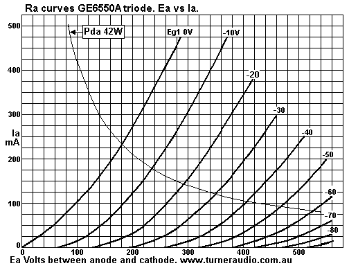
Fig 1 shows 6550 Ra curves from a scan of an ancient GE data sheet
and tidied up in MSPaint.
The positions of the curves have been carefully preserved. Most of
the GE 6550 type A ever made have
been used up and worn out and the few NOS survivors have become
ridiculously priced. The above graph
is typical of a power triode, but it does not convey any
information above 560V. But Va swings can extend
up to 1,000V. You may blame the laziness of the men and women who
tested the tubes and the moronic
publishers of data who refused to produced publications on A4
sized sheets of paper.
Many triodes amps with 6550 may have Ea at +450V, and a high value
load may swing the anode
Vac by +/- 370Vpk, so Vapk swings up to 820V should fit on the
curve sheets. The graph looks like there
may have been more info available in 1960, but the accountants
reduced the size to fit a small cheaper
book page size. Or else the testing methods at GE were quite
limited, which I much doubt. Big companies
like RCA and GE did spend a lot on testing their products to get
the best characteristics, reliability and
tube life. Nobody really knows what a COMPLETE set of curves for
ancient GE6550 might look like, but
use of a high reactance choke, say over 20H to feed Idc to a 6550
will allow Ea at +500Vdc, and the Ea
swing can be up to +/- 430Vpk without any R load connected, so max
Ea can reach 930V. With a 1kHz sine
wave input at grid with THD < 0.1%, anode Vac and THD can
measured and the results indicate information
well above 560V which GE have declined to give us. And all this
can be done without excessively
complex gear. See my page at basic-tube-4.html
Most manufacturers in western countries closed down by 1986. The
Russia, Yugoslavia, and China
have continued. Some have published the same curves produced in
1960, rather than produce curves
form their own production which may vary slightly from 1960. A few
manufacturers like Emission Labs
and KR Audio and others have produced curves for their own tubes.
But many data sheets for all types
of triodes, pentodes, beam tetrodes have been at a lower standard
than produced in 1960.
To really understand what any given tube will do, buy sample
and test it yourself. Do not rely solely on
computer modelling and simulation programs. Read all you can from
old books and notes by old
manufacturers.
Ra means "anode resistance" - the resistance you would measure
between anode and cathode if you
varied the anode voltage while keeping cathode at 0V and grid at a
fixed -Vdc. If you had a 6550 in triode
set up with a choke feed for anode, and Ea = 400Vdc, Ia = 70mAdc,
with fixed grid bias Vdc, and 10uF
capacitor from anode to the outside world, a resistance meter will
measure R = infinite because you are
measuring a capacitor, which is an open circuit for Vdc applied to
measure R. But if you connected a 10k
from cap to a signal gene, and applied a 10Vac 1kHz from gene, you
would find about 9.3Vac across 10k,
and 0.7Vac between anode and cathode. The current in 10k = 0.93mA,
and R "looking into" anode
= 0.7V / 0.93mA = 752r.
The 6550 triode will appear to have this resistance at all
frequencies up to about 100kHz when internal
capacitances begin to have some shunting effect on R. The triode
has 400V x 70mAdc flow, but this does
not mean anode resistance = 400V / 0.07A = 5k7. If the Ea was
increased from say 400Vdc to say 420Vdc,
you may measure Iadc increases 26.6mA. The R = Ea change / Ia
change = 20V / 26.6mA = 752r.
The screen and anode connected together have a transconductance,
gm, effect on Ia, in this case Ea
change of +20V causes Ia change 26.6mA, so gm of anode and screen
= 1.33mA/V.
It is simply calculated as 1 / Ra = 1 / 752r = 0.0013A/V =
1.33mA/V. If the screen is taken to a fixed
Vdc of say +300Vdc, then the Ra appears to be about 25k, so how
can this be? The anode gm = 0.04mA/V,
an almost negligible amount. The screen at held at a fixed Vdc
prevents the field effect of anode V change
from altering the Iadc so Ea can be varied with little Ia change.
Thus pentodes and beam tetrodes when
connected as such are considered current sources and anode loads
are less than Ra, while triodes are
voltage sources where anode loads are more than Ra.
The tube curves allow us to plot a suitable load value for pure
class A used in all SE amps.
Each Ra curve is for a fixed value of Eg1 applied to grid. In
1960, curves were drawn by an
electro-mechanical machine which drew the curves on paper. I could
assume tube amps were used to
power the curve plotter. This was not a perfect process, and
errors were produced but in general the errors
were less than the distortion produced by shape of curves of the
tube. Therefore the old data curves
indicate the distortion likely in any given tube plus the
distortion in the measuring and curve plotting gear.
My tests have revealed many tubes are more linear than the old
curves predict.
There are a few online sources which show pictures of oscilloscope
screens but it seems to me that few
people are able to calibrate the curves they generate. Many
attempts at drawing curves for tubes have
been attempted since 1960, but few have ever succeeded to equal
the quality of well calibrated curves
produced by office staff in well funded and equipped factories of
1960.
Each Ra line is a curve and not a straight line because the change
of Ea produces non linear Ia change.
The Ia change = a constant x cube root of Ea squared. The Ea
change alters the anode electrostatic
field and the resultant Ia change follows complex formulas
described in old books written in 1920s and
1930s. One Professor Child wrote a lot about all this and you
might Google Child's Law.
A few people have succeeded in using a PC to very easily create a
digital file of the curves which can
be printed out, and there are some PC programs available now which
automatically plot loadlines across
the tube characteristic Ra curves and calculate the distortions.
Considering the 6550 Ra line in the
above set of curves for Eg = 0V, when Ea is raised to 100V, Ia =
103mA, and you can say Ra = 100V / 103mA
= 970r. But if Ea is increased to 200V, Ia = 275mA, and Ra between
100V and 200V = Ea change / Ia change
= 100V / 172mA = 581r.
But this is not accurate because the Ra starts at maybe 1,160r for
0V to 58V, but then becomes lower as
Ea is raised. Ra for any one Ea and Ia value is never ever known
exactly on the canvas. It is sufficient for
us to know the Ra within a range of probable values. The best
anyone can do is draw a tangent line to
nearest Ra curve to any chosen point, then calculate Ra = Ea
change / Ia change.
So then we know approximate Ra at that chosen point, for small Ea
and Ia changes. All resistances
can be measured in ohms using Ohm's Law, R = V / I. Instead of
typing the Greek letter omega for
ohms, or the word ohms, I type " r " after a number, say 1,160r
and we should all know that is 1,160
ohms, but is also writen as 1k61, or 1.16k.
The DC operation of the tube should be considered separately to
the ac operation. The equivalent
ac model of a triode can be considered a voltage generator with
Rout < 1r0, which generates
Vo = µ x Vg-k, ie amplification factor µ x Vac between grid g1 and
cathode. The anode resistance can
be an imaginary R between generator output and the real anode
terminal which connects to the anode
load RLa. The imagined R works just like Ra.
Fig 2. Testing power triodes.
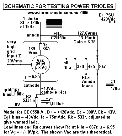
Fig 2 shows Vac Generator Model of a 6550 TRIODE in a simple basic
test circuit to measure its
Ra, µ, and gm for idle Ea = 380V, Ia = 75mAdc, idle Pda = 28.5W,
Eg1 = -40Vdc.
The Ra at the idle point = 867r, and µ for Vg change of +/- 10Vpk
= 6.95.
Gm = µ / Ra = 6.95 / 867r = 8.016mA/V.
There is additional info on measurement of tube parameters Ra, µ
and gm at basic-tube-4.html
The choke is as high an L value as might be afforded. The Rw
should be < 200r. Two or three
chokes of different values can be used in series. But I used one
big choke with reactance XL at
1kHz above 200k ( L = 32H+ at 1kHz ) so that loading effect on
triode was negligible. So when
such a choke is connected without any RLa the Iac is extremely low
and amplification µ is at its
maximum value. In other words, the loadline without any RLa
connected at selector switch is a
nearly horizontal line. The Vac input may be increased until
oscilloscope shows waves just less
than clipping on positive or negative wave peaks, or both.
THD can be measured by by sampling anode Vac after C2 using a high
resistance divider of say
2M0 : 220k giving about 10:1 Vac reduction.
Fig 3. 7k8, 3k9, 1k9 loadlines for SET 6550EH.
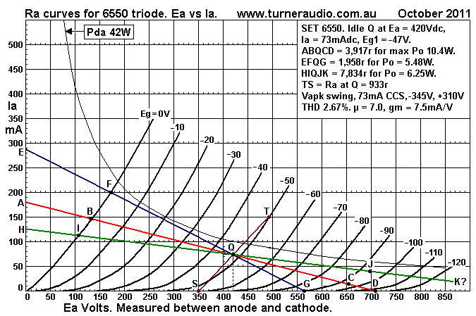
Fig 3 shows 3 loadlines for a single EH 6550 triode with Ea =
420Vdc, Ia = 73.4mAdc,
Eg1 bias = -47Vdc, Pda = 30.66W = 0.73 x Pda max of 42W.
1. Plot point Q at 420V x 73mA.
2. Calculate RLa load for maximum pure class A Po for the chosen Q
point :-
Examine Ra curves, and plot B at twice Iadc at Q on Ra curve for
Eg = 0V, ie, at Ia = 146mA.
This is found to be at Ea = 134V.
The average resistance value between 00 and B = V / I = 134V /
146mA = 918r.
RLa for max class A Po = ( Ea / Iadc ) - ( 2 x Ra at g1 0V ) = (
420V / 0.073 ) - ( 2 x 918 )
= 5,753r - 1,836r = 3,917r.
3. Calculate for point A :- ( Ea / RLa ) + idle Iadc = ( 420V /
3,917r ) + 73mA = 107mA + 73mA
= 180mA.
Plot point A at 0V x 180mA.
4. Calculate for point D :- V across RLa for Iadc = 3,917r x 73mA
= 285.9V. Add Ea, = 705.9V.
Plot D at 706V x 0.0mA.
5. Draw straight line from A to D. This should pass through B and
Q. If not, repeat everything
until this occurs.
6. Plot C on QD where Eg1 = twice Eg1 at Q. Eg1 at Q = -47V, Eg1
at D = -94V.
The line BQC is the load line for 3.917k
7. Calculate 2H from line BQC. B to Q = 134V to 420V = 286Vpk Ea
swing.
Q to C = 420V
to 655V = 235V. 2H = 100% x 0.5 ( BQ - QC ) / ( BQ + QC = 100% x
0.5 x 51V / 521V
= 4.90%.
8. The Vpk-pk = B 134V to = C 655V = 521Vpk-pk ; Va = 521Vpk-pk.
Vac = 521 / 2.828
= 184Vrms.
Calculate Po = Va squared / RLa = 184 x 184 / 3,917r =
8.65W.
9. Conclusions. Po max occurs at onset of clipping where Ea swing
reaches Ra line for
Eg1 = 0V, and Ea swing max is determined by reducing gm of triode
with low Ia which
prevents Ea max swing reaching D.
Po with low THD can only be increased slightly if enough NFB is
applied. 16dB NFB should
reduce THD from 5% to say 1% and allow Po max to reach nearly 10W.
The grid Vac will
contain about 4% THD with opposite phase to reduce output THD to
1% at about 10W.
In practice, expect Iadc to increase slightly with continuous sine
waves and cathode biasing.
The Ek will rise a few Vdc, indicating the 2H is causing some
"rectification" effects.
The Ea will stay nearly the same, but the Po can increase with
Iadc idle point raised higher.
With fixed Eg1 bias Vdc, the rise of Q point and increase of Iadc
is lessened. In music amps
the average Po is perhaps 1/20 of the clipping level so there
there is no need to concern
ourselves with a shifting bias point at high levels.
Theoretical max class A Po for the RLa calculated
= 0.5 x Iadc squared x RLa = 0.5 x 0.073 x 0.073 x 3,917r
= 10.44W. When enough NFB is used, clipping should occur
symmetrically on +/- wave peaks,
and if you measure 10W you are doing well, for THD < 2% with
NFB.
For all RLa loads higher than RLa for max Po, clipping occurs on
negative Va peaks;
the Ea swing cannot move to the left of Ra curve for Eg1 = 0V, and
Po is less. For all RLa loads
lower than RLa for max Po, clipping occurs on positive Va peaks;
the Ea swing cannot move to
a negative Va below line for 0.0mA, and Po is less.
10. All SE amps should be able to power speaker loads which vary
between 0.5 and 2.0 times
the load for max class A Po. The anode Po is well below maximum
possible but there can be
enough for good listening. A typical OPT for SE operation may have
7% winding losses for
the load for maximum class A, so at OPT sec Po = 9.3W.
Where load = 1k9, losses are 14%, Po = 4.3W. Expect 6W with RLa =
7k8.
Graph 1. Po vs RLa, SET KT120, 6550, 300B.
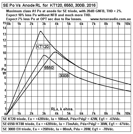
Graph 1 shows the available SE triode Po from from 1 x KT120, 6550
or 300B.
KT120 gives 14W max Po because it has idle Pda = 40W, and anode
efficiency = 35%,
good for SE triode. OPT is 4k0 : 4r0, 8r0, 16r0 for the 420V x
100mA idle condition.
8W is available for 1k5 to 6k0.
6550 or KT88 give 10W max Po with idle Pda = 30W, anode efficiency
30%.
OPT is 5k0 : 4r0, 8r0, 16r0 for 420V x 73mA idle condition. 6W is
available between 2k2
and 8k0.
300B EH gives 10W max with idle Pda = 28W, anode efficiency = 35%.
Ea can be lower
at +350Vdc.
There is little performance difference between a 300B EH and a
6550 / KT88. OPT load
can be 4k0 : 4r0, 8r0, 16 for the 350V x 80mA idle condition. 6W
is available from 1k7 to 5k8.
The damping factor with all these SE triodes is good even with
zero GNFB. The best sound
is possible with higher RLa than the OPT values quoted, and with
sensitive speakers. A 6r0
speaker would be used on 4r0 output terminals. For more Po with
better fidelity with average
speakers with low sensitivity, use more than 1 triode, and a
speaker giving 90dB SPL will
need 4 triodes instead of just one with a speaker rated at 96dB.
------------------------------------------------------------------------------------------------------------------------
I have found many power triodes are capable of less than 2.7% 2H
at high Va where the RLa
load is a constant current source, or more simply a large amount
of inductive reactance with a
large choke.
So were the curves drawn in 1955 correct? I decided to measure a
couple of slightly used
EH6550 to see if there was much difference between Russian made
EH6550 for 2006 and the
GE 6550A made all those years ago in the USA.
Fig 4. 3k0, 4k5, 9k7 Loadlines for SE 6550 triode.
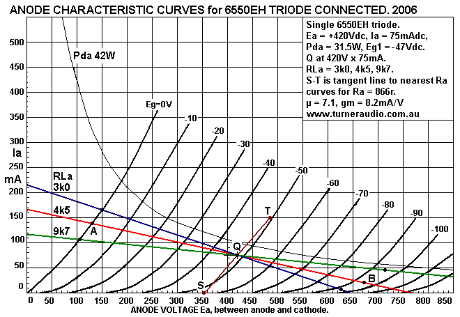
Fig 4 has 3 load lines used with 4 different tubes to test
differences in THD.
Fig 2 from above shows the basic schematic I used to test EH6550,
GE6550A, KT88JJ,
and KT90.
The choke > 20H and supplied Idc to anode while acting as a
virtual constant current source
because even with 250Vrms at anode and XL = 100k, Iac = 2.5mA and
load would be a nearly
horizontal line. Negligible phase shift is present because all the
triodes have Ra < 1k0.
The original test schematic had switched anode resistor loads 9k7,
7k2, 4k5, 3k0, 3k0, 1k0.
Cathode resistors were also switched to vary cathode bias to a
wanted value. There is a low
distortion signal amp for grid signals producing less than 0.5% 2H
at 50Vrms.
The 1kHz test signal from 1kHz oscillator has 0.005% THD. Since
2006, I upgraded the test
schematic as seen at basic-tube-4.html
The conditions for the test were Ea = 420V, Ia = 73mA, Eg = -47V,
approximately.
Here are three following graph sheets each with the same 3 loads
showing measured THD for
each load vs output voltage.
Fig 5. THD vs Va graphs for EH6550 and GE6550A triode.
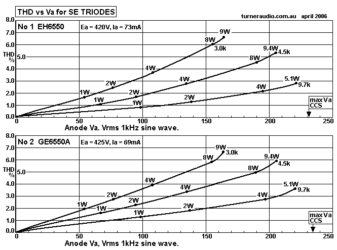
With no load connected, 2H < 1.6% at 235Vrms output. This
indicates old Ra curves for
GE6550A were not correct, at least for EH6550, which appear to be
more linear than the
old curves indicate.
Fig 6. THD Vs Va for JJ KT88 and KT90.
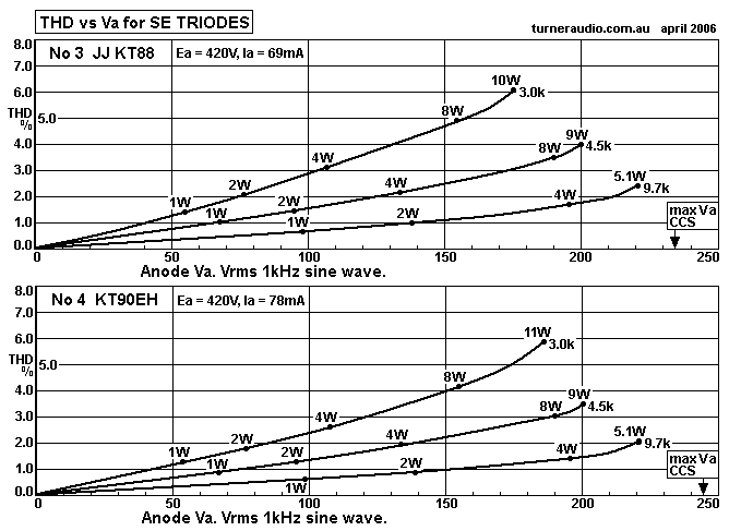
The JJ KT88 measured almost identically to 6550EH and GE6550A. I
have found all
Russian 6550 and KT88 including Sovtek have negligible performance
data, and the
internals for Sovtek and EH tubes look exactly the same. The
glassware was changed after
Mike Mathews formed joint venture with former Soviet factory
Sovtek which had been
making many military tubes. Many buyers preferred tubes which did
not remind them of
social communist Russia and the cold had fact that USA tube
factories closed down and left
thousands of owners of guitar amps without a source for new tubes.
DON'T WORRY, all these beam tetrodes make wonderful music when
triode connected.
All produce less than 2% 2H at about 2W for the Middle load of
4k5.
You can easily get 9W with Pda at 30W, 2H between 4% and 5%. GNFB
can reduce this to
under 0.5% for excellent music with sensitive speakers. For
average speakers of 88dB/W/M,
use of 4 x EH6550 give 36W easily. 12dB GNFB gives THD < 1.0%
at 32W, and 0.13% at
1W which would produce 88dB with two amps. For average levels of
85dB SPL, THD < 0.1%
and the SE triodes will not sound worse than many PP amps which
will measure less THD.
Loading may be calculated for design without concern for winding
resistance where it is less
than 10% of the RLa. Total SE OPT winding resistance for the
middle load value may be 7%
so that if RLa = 5k0, Rw may be 350r. This makes little difference
to the music. But instead of
getting 9W, you get 8.4W. A typical good SE OPT will have Rw <
7% for the Nominal RLa.
The Rw of any OPT cannot easily be measured. Consider OPT for 5k0
: 8r0. The primary
winding may have winding resistance = 150r which is 3% of primary
RLa = 5k0. The secondary
may have Rw = 0.28r. This is 3.5% of the sec load. The OPT has ZR
= 625 : 1, and the sec Rw
is transformed to become 175r at primary and total Rw input at
primary
= 150r + 175r = 325r. Therefore the load at anode = 5,325r, If we
assume 9W is applied to this
load, then power lost as heat in total Rw = 100% x 325 / 5,325r =
6.1%, and instead of 9W at
speaker, there is 8.45W. Be satisfied. This loss is is tiny when
compared to life's big issue losses.
To reduce Rw loss to 3% may involve an OPT that is 3 times the
weight and cost, and it won't
sound better.
If the RLa = 5k0, and triode Ra = 950r, and Rw = 325r, then total
R in series with load
= Ra + Rw = 950r + 332r = 1,275r. The damping factor = load R /
total series Ra + Rw
= 5k0 / 1k275 = 3.92.
This is is good enough to not use NFB. But where 12 dB NFB is
used, expect DF to increase to 15.
---------------------------------------------------------------------------------------------------------------------------
Fig 7. GE6550A Ra curves extended after my tests.
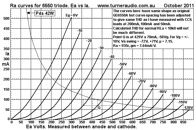
The people who have come to understand the meaning of Ra curves
and load lines will notice
how Ra curves of all triodes including 6550 tend to become closer
together on the right side of
graph, especially where Ia < 50mA. This means the tube needs
more grid Vac change at low Ia
to swing the same Va as it does above Q to get a Va change. The
most linear transfer function
between Vg and Va occurs when RLa is a CCS, a horizontal line
across the Ra curves, or at
least 100 x Ra. This loading allows maximum possible Va swing,
lowest Ia swing, and least THD.
I have plotted a point Q at a convenient position on Ra curve for
Vg = -50Vdc. IQ is at 429V x 70mA,
and at Pda = 30W, and where the 6550 could be used. If you plotted
a horizontal load line through
Q at 70mA, you would find Ea swings down to 70V and up to 772V for
Vg swings of +/- 50Vpk.
The anode swings -359V and +343V.
2H = 0.5% x ( 359 - 343 ) / ( 359 + 343 ) = 1.1%.
There are other H, but they will be less than 0.7% and make little
difference to THD.
All finite resistance loads above the infinite R value of a
horizontal load line will generate higher THD.
The amplification factor µ = tube gain for RLa = CCS. Gain for
6550 triode over a wide
Va-a = Va pk-pk / Vg pk-pk = 702V / 100V = 7.02. This is average
gain, and average µ for a CCS
load, ie, constant Ia = 70mA. The max Va = 702V / 2.828 =
248.2Vrms.
But the triode will spend 90% of its life operating with very low
Po and low Ea & Ia swings.
If we look closely at Fig 7 you see point Q at 429V x 70mA. For Vg
swings of +/- 10V peak the Va
swings are -71V and +72V. µ = ( 71 + 72 ) / ( 10 + 10 ) = 7.15,
slightly higher than average.
The 2H becomes difficult to calculate with such small Vac from a
graph which may have errors.
But 2H would be 0.5% x 1 / 143 = 0.7%, far more than what we may
expect because usually the
2H is proportional to Va. We might expect 0.22%. I calculated Ra
at Q = 935r. Gm = 7.64mA/V.
------------------------------------------------------------------------------------------------------------------------
Fig 8. Ra curves for KT120 triode.
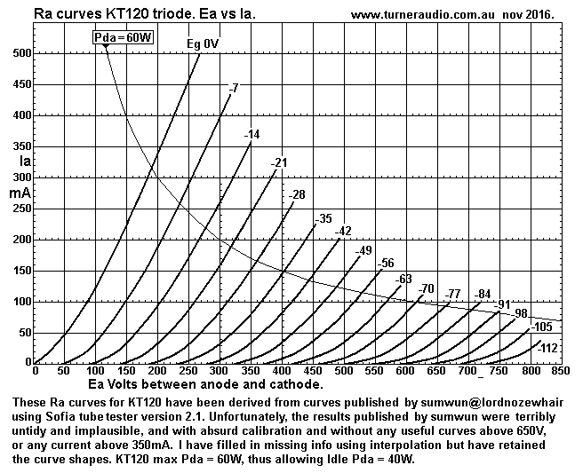
KT120 is very similar to 6550 EH or KT88 EH. The Pda max is 60W,
so more Po is available.
The Ra curve for Eg1 = 0V is slightly steeper than 6550EH so Ra is
lower for this curve.
But for a Q point at about 435V x 70mA, Eg1 = -49V, Ra = 925r, and
hardly any different to 6550.
If I plot a CCS line at 70mA, I get Ea swing -365V and + 335V for
+/- 49V swing of Eg1.
The average µ = 700Vpk-pk / 98Vpk-pk = 7.14, same as 6550 !
2H along 70mA line = 100% x 0.5 ( 365 - 335 ) / 700 = 2.14%. Maybe
the curves are correct enough.
Fig 9. KT120 with RLa 1k4, 2k8, 5k6.
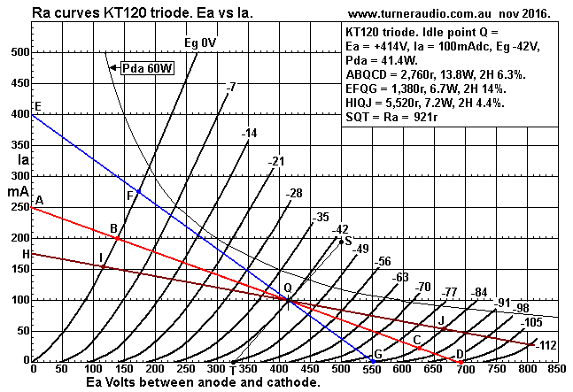
The load for max possible class A Po = BQC = 2.76k, 2H = 6.3% at
13.8W.
Load FQG = 1.38k, 2H = 14.0% at 6.7W, and Load IQJ = 5.52k, 2H =
4.4% at 7.2W.
With R&C cathode biasing, the cathode Ek will rise when low
loads are used with sustained
sine waves at high levels because positive going peak currents are
higher than the negative
going currents. This is called the "rectification" effect. This
means the Idc of the tube
increases increase of DC power from PSU.
The maximum output power for loads below 2.76k become higher than
indicated on my
Graph 1 for Po vs RLa for KT120 and other triodes. Where fixed
bias is used to grid with
cathode to 0V, and where 20dB GNFB is used, there is no shift in
bias Idc for tube. The NFB
cannot correct the 2H where the anode current cuts off. Therefore
max Po for low load 1.38k
can be calculated as 0.5 x Iadc squared x RLa = 0.5 x 0.1 x 0.1 x
1,380 = 6.9W. For a very
low RLa = 100r, peak Va swing = +/- 100mA, Po = 0.5W, with Vg
limited to +/-21Vpk. For 100r,
with less Ia swing, say +60mA -50mA, Po = 0.15W, and 2H = 9%. But
for higher Po for 100r,
the THD becomes similar to a half wave rectified signal in a PSU,
and this disqualifies the Po
as being acceptable. The Graph 1 figures are for THD < 2% and
with 20dB GNFB, and no OPT
winding resistance losses, ie, RLa load is between anode and 0V
via C with low reactance.
-----------------------------------------------------------------------------------------------------------------------
How good is the EH6550 or KT120 in triode compared to the "gold
standard" of power triodes,
the 300B?
I don't have a WE 300B to test but here are some curves I found
from www.audiomatica.com,
measured on a Sofia tube curve tracer before 2003.
Fig 10.
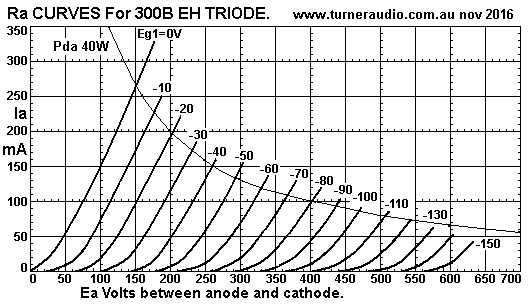
The Ra curves look quite good but their accuracy cannot be
verified until one is tested with
choke with XL > 120k and a real resistance load. I have plotted
ABQCD loadline for 4k5.
The 2H from curves = 3.1%.
If a Q point is plotted at 350V on 80mA horizontal line at Eg =
-70V, Ea swings -285V, +272V
for Eg1 = 0.0V to -140. 2H = 1.2%.
The µ = 3.98. For Q = 350V x 80mA, Ra = 645r. For RLa = 4k5, DF =
6.97.
Fig 11. 300B with 1k5, 3k0, 6k0.
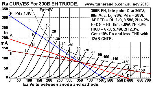
This shows ABQCD load of 3k0 for max possible class A1, and then
1k5 and 6k0 loads
being 1/2 and double. The THD is less than similarly loaded KT120
and 6550.
Emission Labs 300B should give better results.
The reason why 300B is more linear is partly due to its low µ
where the anode to grid and
cathode to grid distances are set up for low Ra, ie, anode has gm
= 1.55mA/V
For 6550 etc, the designers aimed for good beam tetrode
performance and the added screen
has gm of about 1mA/V, so its effect on linearizing Ia is not as
high as the anode in lower µ
triodes invented 25 years before. I am over simplifying the design
issues, but nobody can
deny that the original 300B and modern copies, and developed
versions with higher Pda
ratings, and other triodes such as 45, 2A3 and 845 are quite
magnificent performers with
music.
Fig 12. Emission Labs 300B Ra curves.
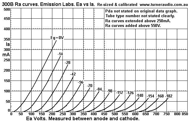
These E.L. curves look very nice, and if an idle point Q was at
390V x 50mA, Eg = -84V,
nd load = CCS, 2H = 2%, and without doctoring up the curves
slightly to allow the big Ea swing
from 65V to 695. What other single amplifying device produces
222Vrms output at less than
2% THD without any external loop of NFB? Not many. All the EM Ra
curves have less curvature
than 6550EH. This means the THD is likely to be lower than for
6550 under comparable load
conditions.
A 6550 in triode has µ = about 6.7. If it was reduced to 3.9 like
a 300B we may find Ra also
reduced to Ra of 300B. I am not a tube design expert, but internal
grid and screen distances
would need tom be changed. There was a a huge effort made to get
the performance we see in
beam tetrode mode and pentodes to allow RF amplification and to
get better plate efficiency
than triodes in class A1 and AB1 and AB2. Use of triode strapping
was always going to be
possible but it was never going to dictate the design for beam
tetrode or pentode mode with a
fixed Eg2.
If you use a 6550 in triode mode with 10% of OPT primary turns in
a cathode feedback winding,
the effective µ is reduced from 6.7 to 4.0, virtually the same as
a 300B. The Ra is reduced from
900r to 538r, and you will find the 6550 in triode has better
operation than 300B, while it needs
about the same grid Vac input as does 300B. I did this in1999 in a
modified Quad-II amp, see
quad2powerampmods.html
This mod gave 20W in class AB1 triode, and everyone said the amp
sounded better than the
original Quad-II. The idea of CFB works just fine in SE amps. But
there isn't any need to use
CFB with 300B because it is already just fine without any local
loop NFB.
I have a pair of KR audio 300B which have Pda = 50W, NOS, made in
about 2007, and I did
lend them to two audiophiles in about 2009 to see if they could
hear anything better than what
they already had, ie, Svetlana Winged C 300B, and Sovtek. They
heard no differences.
They could hear no reason to pay the huge price for KR300B. I
concluded their interest in
Ultra High End tubes was lessened by me lending them a pair of the
world's supposed best
300B on offer. I can say that in 2016, KR Audio and Emission Labs
prices will punch a big hole
in your wallet. Are the exotic high end tubes better made? The KR
and Emission Labs tubes do
look better when you see one and feel better in your hands; they
are heavier, the glass is thicker.
But these factors along with the cosmetic appearance does not make
them any more likely to
give better sound than a JJ300B, or a Sovtek 300B. JJ300B price is
less than 10% of Emission
Labs.
So you could easily use 3 x JJ300B in parallel for 24W and I see
no reason why the sound could
be worse than use of a single 845 made by the most expensive brand
name.
-----------------------------------------------------------------------------------------------------------------
Fig 13
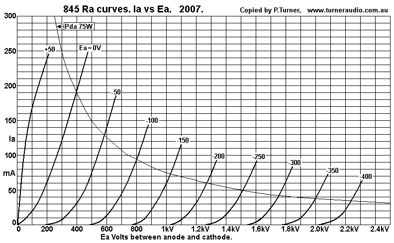
Fig 13 shows the magnificent Ra curves for an 845.
Consider horizontal line at 50mA from Ea = 180V to 2,285V, and Eg1
from 0V to -400V.
Average µ = Ea change / Eg1 change = 2,285 / 400 = 5.713.
Ra at 1kV and 50mA = 2k2. Ea at Eg1 = -200V is 1,247V. For Vg =
+/-200Vpk, Va = -1067Vpk,
+1038Vpk, 2H = 0.64%, which seems too good to be true, but without
any Ia change, 845 triodes
are remarkably linear.
The Ra is much higher than 6550-KT120-300B but is low compared to
the ideal class A load
RLa for the idle conditions. If the idle condition was 1,000V x
50mA, Pda = 50W, RLa for max
class A = 15k6, Po = 19.5W, with 12dB GNFB. Without GNFB, DF = RL
/ RLa = 15k6 / 2k2
= 7.09, quite good, but with GNFB it will be about 30!
6dB GNFB would be plenty, and some would say no NFB is needed. The
OPT is 15k : 4r, 8r,
16r, and must be custom wound very carefully to get enough
bandwidth.
Consider the horizontal line for Ea = 70mA from Ea 215V to 2,320V,
Eg1 0V to -400V.
Average µ = 2,320 / 400 = 5.80. Ra at 1,050V and 70mA = 1k9.
Let us try idle point at 1,050V x 70mA, Pda = 73.5W. At Eg1 =
-200V, Ea would be at 1,297V.
Without any Ia change, For Vg = +/-200Vpk, Va = -1082V, +1023V, 2H
= 1.3%. The THD with
loads will be higher. RLa for max class A load = 11k2, Po = 27.4W
with 12dB GNFB.
Without GNFB, DF = 5.8, but with 12dB GNFB, DF = about 25.
Class A RLa are calculated here approximately = ( Ea / Ia ) - ( 2
x Ra ) where Ra is at the
idle Q point. The Ra curve for Eg1 = 0V is well curved between 0mA
and 140mA, the Ea change
= 325V, so you cannot assume Ra = 325 / 0.14 = 2k3, which is
higher than at the Q point
1,050V x 50mAdc.
Let us see the load lines for Q point 1,050V x 50mAdc.........
Fig 14. SE845 with RLa 9k0, 12k0, 18k0, as in SE55 amps with 2 x 845
parallel.
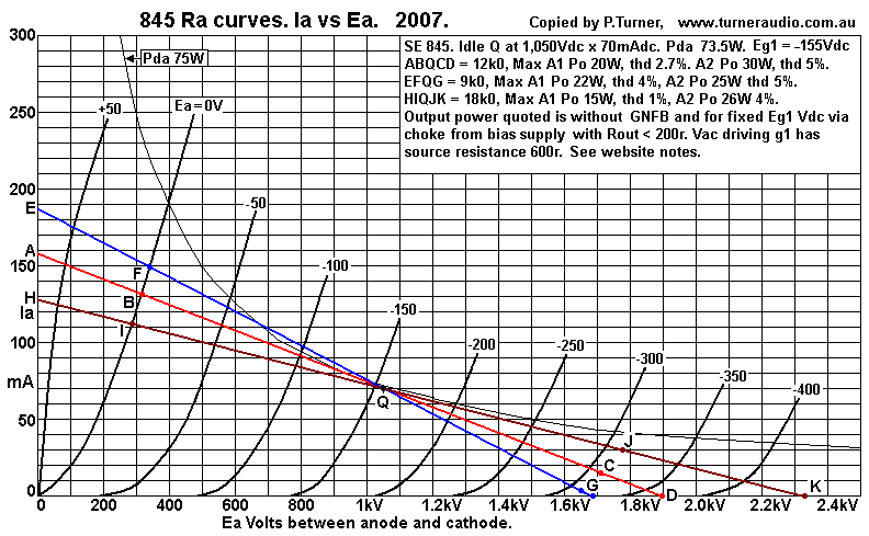
Fig 14 shows 3 RLa values for Idle point 1,050V x 70mAdc = 73.5W.
This idle point
is safe with KR Audio 845 because they are rated for 100W max. But
they also have
heater power = 10V x 1A with oxide coated directly heated cathode,
so cathode heat = 10W.
Total heat = 83.5W. Other 845 from Shuguang which are closer
copies to original RCA
845 have tungsten cathodes needing 10V x 3.3A = 33W. Some will say
idle Pda may be
100W, but this may not be reliable. The max Pda rating listed in
data may be 100W, but
95% of 845 were used in PP class AB1 for audio modulating AM radio
transmitters which
may have also used 845 for RF output running in class B or class
C.
The working average Pda for all these applications was always kept
lower than 100W
because of the expense of tube replacement.
In 2008, built a pair of 55W monoblocs with a pair of 845 in
parallel. They used KR Audio 845,
and I used 3 x EL84 in triode and parallel as the driver. The 700
hour design and construction
time was not in vain. These amps were excellent with music. The
fussy customer who bought
the 55W amps heard no difference between expensive KR Audio 845
and Shuguang type B at
about 1/4 of the price. The Shuguang in 2008 was a more accurate
copy of original RCA 845
with thoriated tungsten cathode which makes it last longer with
typical idle Ea = up to 1,300Vdc,
common in PP amps with Ia at 30mA for idle Pda = 39W. For pure
class A1 or A2, I figured the
best idle point was 1,050Vdc x 70mAdc for each 845. Power output
and THD for both KR Audio
and Shuguang 845 were not much different. My efforts with SE 845
are seen at
monobloc845se55.html
The OPT for the SE55 amps has OPT with 4 load ratios = 5.88k
: 4r0, 6r3, 9r0, 16r0,
with 9 sec windings strapped in 4 different combinations of series
and parallel. Consider use of
OPT strapping for 5.88k : 4r0. The total winding resistance at OPT
input = 277r. Therefore the
anodes must work with primary load = 6.14k. Speaker Z is never a
constant R at all F, and a
"4 ohm" speaker may vary between 3r0 and 30r, with probable
"average Z" or nominal Z = 4r0
between say 80Hz and 800Hz where most music energy exists. The Z
variation within 80Hz to
800Hz F band may be 3r0 to 6r0, and resulting anode load is
between 4k5 and 9k0 for the pair
of 845, with 6k0 being the Nominal average RLa.
This means each 845 has loading between 9k0 and 18k0 with a
nominal RLa = 12k0, as shown
in Fig 14 above.
Fig 15. 1 x 845, Po vs RLa, two idle conditions.
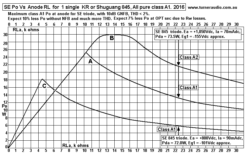
Fig 15 has 3 curves for two idle conditions.
A and B are for idle condition 1,050V x 70mA, and C is for 800Vdc
x 90mAdc,
Curves A and B show what happens with one 845 in SE55 at monobloc845se55.html
I found the SE55 could make absolute max Po of 60W with 30W from
each 845. This is only
possible by pushing the tube beyond class A1 and into class A2
operation which means driving
the grid 50V above 0V, with Vg = 141Vrms, or +/- 200Vpk. During
class A2, grid current flows for
25% of the positive Vg going wave.
I used 3 x EL84 triodes paralleled to give source resistance 700r,
so the driver can drive the low
grid input resistance with grid current. During A2, the coupling
caps will charge to make grid bias
slightly more negative. I found that I could still get 30W from
each 845, ie, 60W from the pair with
a continuous sine wave.
THD becomes slightly too high but I estimated that with music and
before the charge in coupling
caps changed, wave peaks could be dealt with in class A2 without
high THD.
Text books suggest all class A2 drive must be from direct coupled
cathode follower or from a
transformer winding taken to a low resistance bias Vdc source.
The use of a coil of wire to bias
output tubes prevents any grid bias change due to grid current.
Such a coil adds a time constant,
threatens LF stability. C&R coupling is fine for A1, and I
found is OK for a slight amount of A2.
Use of 211 tubes means the amount of A2 is much greater so
ordinary C + R grid drive does
not work so well.
Maximum theoretical class A1 Po with THD < 2% with GNFB is 25W
with anode RLa 10k3.
All loads below 10k3 have Ia swing limited to +/- 70mApk. No class
A2 can boost Po for these
lower RLa. But for loads above 10k3, the Ia swing in class A1
begins to decline because Va
swing is limited by Ra curve for Eg1 = 0V, ie, the triode's "diode
line" But Class A2 can boost
Po higher for the higher RLa by pushing grid positive to allow
greater Va without Ia cut off,
hence Po max can be 30W in class A2, with anode efficiency
reaching 41%, similar to a beam
tetrode.
Curve B shows the Po vs RLa for 1 x 845 with idle Ea 800Vdc x
90mAdc. The Pda = 72W.
But max Po is 18W, and anode efficiency = 25%, and this is the
classic example for feeble
class A1 triode Po. However, the 18W is with RLa 4k5, and an OPT
for say 5k0 :4r0, 8r0,
16r0 can more easily be found. DF will be only just over 2.0, and
THD is probably 5%. 18W
is very adequate Po for may hi-fi enthusiasts. If 12dB GNFB is
used, expect sound to be very
good.
Fig 16. SE 845 with RLa 5k5, 10k4, 22k0.
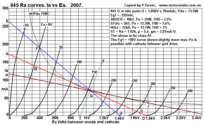
Fig 16 shows ABQCD loadline for 10k4, and probably the load which
gives maximum
class A1 Po. If BQ = QC, then there is exactly +/-70mA change for
Po 25.5W, with GNFB.
But we never will see BQ = QC for any triode where the input grid
Vac has THD < 0.1%.
Loadline ABQCD has BQC for class A1 and RLa = 10k4, Ea min = 335V,
Ia = 140mA.
Ea max =1,680V.
Ia swings are +70mA, -61mA.
The Vapk = -728pk, +624Vpk, = 1,352Vpk-pk = 478Vrms, Po =
22W. 2H is 3.85%.
The use of a driver triode with say 2% 2H reduces 845 2H to 1.95%,
and 12dB GNFB could
reduce this to less than 0.5%, to produce Ia swings +70mApk,
-68mApk, to give Vapk-pk =
1,456Vpk-pk = 514.9Vrms for Po = 25.5W.
I have max class A1 Po at 25.0W in Fig 15 graph.
All of this is a guide only. But let us assume your attempt to
build an amp with 1 x 845 gives
25W at the same 10k4 RLa and same Ea x Ia idle conditions. Expect
to measure THD somewhere
between 0.5% and 2%, even with 12dB GNFB. The popular choice of a
driver tube for 845 is
an EL34 triode, with Ia say 30mA, set up with choke feed similar
to my SE55, but with Ea at
+400Vdc. Its 2H production may be different to my use of 3 x EL84
in parallel.
Use of a nominal RLa = 12k0 ( Fig 14 ) instead of 10k4 will give
Ia swings +62mApk, -56mApk,
for A1 Po = 20.8W, THD = 2.65. With GNFB, THD 0.5%, expect Po
22.3W. But if the grid is
pushed to +22V, and with NFB, the the Ia swing can be increased to
+/-70mApk, -68mApk,
and Po = 28.5W.
If the RLa = 22k, ( Fig 16 ), load line HIQJ, the class A1 Ia
swings are +35mApk, -34mApk,
Po = 12.7W, and GNFB would raise this to 13.5W and about what is
shown in Fig 15 graph.
THD should be less than 0.5%. The HIQJ line shows Vg could be
pushed to +50Vdc for Ia
swings +45mApk, -44mApk, Po = 21.8W, increasing max Po x 1.6 over
the class A1 Po max.
2H beyond class 1 and up to limit of class A2 will increase
slightly, but there will be more 3H
because of gradual Va limiting before clipping when many HD begin
to be produced to
increase THD exponentially.
In the SE55, I was able to get 60W at the output terminals from
the pair of 845 with partial
class A2 operation, and OPT losses were estimated at 4%, so there
was 62.4W at anodes,
and I didn't bother measuring Ek to see if Ek had risen say +15Vdc
to increase Iadc to say
76mAdc. The tests to obtain the 60W result were done with
continuous 1kHz sine wave up
to just over the clipping level. To better simulate performance
with music, it is best to use pink
noise with its bandwidth limited for 20Hz to 20kHz. When your CRO
shows occasional clipping
at peaks of noise, you have reached the maximum level possible for
the amp without any
clipping seriously affecting hi-fi musical performance.
For an amp rated for 60W for 4r0, Vo max = 15.5Vrms for a sine
wave. But you will find that
a pink noise signal will produce occasional small amounts of
clipping when measured Vrms
= 5Vrms, ie, at -10dB below Vo level, and when Po = 6W. If you
played music signals which
measured 6W with a meter, you'd soon find just how loud that is
with speakers rated for
90dB/W/M, because you would have average level of 101dB SPL, way
above what is
acceptable at a live orchestral concert at best seat in the venue
and with average SPL at 85dB.
When all amps are measured this way, a 300W amp has reached the
point of musical clipping
when average level reaches 30W.
A single EL34 in triode making 5W max will operate at max for
hi-fi when Po = 0.6W.
I find excellent music is possible with a speaker rated at
90dB/W/M and only 1M away. I can
tune from one FM radio station to another, from a piano recital or
popitty-krappity peurile music
with the SAME measured level, but including much bass, and it all
sounds well. But a single
EL84 in pentode mode making the same level tends to sound like it
is struggling.
I know a guy who has 845 amps with just 1 x 845 for about 20W max,
and I doubt he ever
uses more than 2W, so Po mas is enough.
The 845 will sound a bit better than a single 6550. The use of 845
is not for high Po and it is
about sound quality at low to medium Po.
The purpose is to be able to hear music which is emotionally
engaging. Tubes do this very well.
And it is almost impossible to make a bad sounding triode amp,
providing it is used well below
clipping levels. The maximum Po for the amp is often cited as
being important when buying an amp.
There is a huge sub-conscious reluctance to buy low power costing
a high number of $$$$.
90% of listeners have no idea how small power levels are during
normal long listening sessions
with music or home theater. I once had a customer who had two
Yamaha 2200 solid state power
amps each good for 200W per channel to drive a pair of huge JBL
monitor speakers each with
2 x 15" woofers plus horn HF units rated for 95dB/W/M - in a tiny
room about 4M x 4M.
I was called in to test one of the beryllium coned tweeters in
horns which was found to have
cracked with metal fatigue. I suggested he try a pair of 20W tube
amps. He may have been
surprised, and I said a single 300B would be fine for both
channels But he was so prejudiced
against tubes that he turned down this idea when I gently
suggested it. OK. He spent 10 hours
in a gym each week, so he liked his possessions to have power like
his body.
Each unto their own. How power is used is the interesting issue
IMHO.
The Po available from 845 is similar to what may be had from a
211. The 211 requires similar
idle Ea and Ia conditions because its Pda max rating is the same
as 845. 211 definitely needs
cathode follower grid drive, but gives a suitable initial amount
of class A1 Po before class A2
action commences.
Afaik, all 211 have tungsten cathodes and definitely are quite
safe to use with Ea at idle
= 1,250Vdc and Ia = 60mAdc for Pda = 75W. Fixed Eg1 bias should be
used. The high Ea
means there is no need to use a cathode follower driver; you will
get a nice 20W in class A1,
but you need RLa = 20k. Very few SE OPTs have been made to suit a
20k primary load.
-------------------------------------------------------------------------------------------------------------------------
Fig 17. GM70. Ra curves, Ea vs Ia.
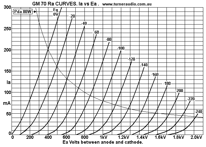
I have not built an amp with GM70, but it deserves a mention. It
has Ra similar to an 845,
but curves indicate µ = 8.0 and gm about 1.5 times 845. So whoever
designed GM70 made
a more gutsy version of 845. The higher gm indicate more cathode
emission than 845, and
GM70 needs nearly twice the heating power to give the emission
from thoriated tungsten
cathode, 20V x 3A, more than the 10V x 3.3A for 845. So 60W is
needed just to warm GM70.
The GM70 Pda rating for continuous operation = 125W, with 150W
stated as OK if not
sustained for more than 1 minute. One would assume that after
being at 150W for 1 minute,
it should have no power for the next minute. 125W is a lot for any
SE class A when you
consider total heat including cathode will be 165W. GM70 was
developed well after the 845
and its production history is not widely known. It is known that
it had a short service life in
typical military applications where the costs of tube longevity
were not important where an
important job function was to be achieved. Typical life was 1,000
hours which we may
base on 125W Pda. If an audiophile uses the tube for 5 hours
a day, expect GM70 to last
only 6 months. But if idle Pda = 70W, we might expect twice the
lifetime so maybe you get
1 year of life. This is about 1/5 of what I have seen for many
other power tubes. 4 x EL34
in triode will do slightly more than one GM70, 845, 211, or 13E1,
perhaps be a lot cheaper
and less worry over time.
I show GM70 Pda curve for 80W which is probably safe for SE class
A1.
The Ra at 80mA and 1kV = 1k9. The spacing between Ra curves from
Eg 0V to -240V is
fairly constant, so the 2H along horizontal Ia lines at 50mA,
100mA and 150mA is probably
< 1%. For Q at 1,000V x 80mA, and where Eg = -100V, and for Vg
= +/-100Vpk, Va swings
= -802Vpk, +798Vpk. Average µ = Vapk-pk / Vgpk-pk = 1,600V / 200V
= 8.0.
gm = µ / Ra = 8.0 / 1,900r = 4.2mA/V.
My Ra graph is not what I have measured but is very carefully
copied from an online data
sheet which does not have any source identification. The tiny
amount of online data
accompanying the Ra curves has gm 6mA/V at 1,000V x 125mA where
curves tell me Ra = 1k8.
If that is true, µ = gm x Ra = 0.006 x 1,800r = 10.8, and this
cannot be true because the µ at
125mA will not me much more than 8.0 at 80mA. So the data words
are bullshit.
There is SO MUCH BULLSHIT online than if you believe it all, you
are a fool. From the small
amount of data available, and the plausible accounts of use of
GM70, I can show some load
lines....
Fig 18. GM70, RLa = 7k0, 9k6, 14k0, at +980Vdc x 70mAdc, Eg1 =
-100Vdc.
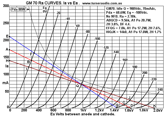
GM70 seems to have very nice Ra curves like 845, and THD for the 3
different RLa is
what we can expect from a good triode. Idle Pda = 980V x 70mA =
68.6W. ABQCD is the
line for maximum class A1 Po, and driving grid positive for a
small amount of class A2 will
not increase Po very much. The 14k0 load can only give 17W in A1,
but with 12dB NFB
and a driver with some 2H could be extend the Va swing to so that
Ia can be +/- 63mApk
so Po could reach 27W.
One website online page at jac.music talks about GM70 being much
better than 845.
There is no date on the article, no contact email address, just a
subscription panel to get
e-mail from them. The author at this site says 845 MUST NOT be
idled above 75W. I agree.
But then he says that the reason is that during class A SE use,
the anode signal current flows
in Ra "which is within the anode" and heats the anode to well over
75W.
Well, we all know Pd = I squared x R. But he is quite wrong,
because during all class A action
the power from PSU remains constant at say 75W, and when the tube
makes 20W of audio
power, the tube heat reduces to 55W; the anode runs cooler. The
idea that Pda with Vac
signal increases during class A is 100% bullshit. The Pda
increases only in class AB, B or C amps.
The current in Ra has an average level which reduces during class
A. The heat of the tube is
just the effect of electrons flowing from cathode to anode and
heat is radiated as a result.
The anode is a metal box with very low resistance and the Pda due
to current flow in anode
is negligible, so heat must be radiated from the empty space with
electrons, and from the
conversion of kinetic energy of speedy electrons when they hit the
anode and are absorbed.
All electron flows in space or in materials such as silicon in SS
devices and in wire, and
resistance all cause heat to be generated, and lost as wasted
energy.
In GM70 without any Vac, you have a flow of 70mAdc across empty
space with 980Vdc
difference, so DC resistance = 980V / 0.07A = 14.0k. The heat
liberated = 980V x 0.07A
= 68.6W. At DC, the GM70 acts just like a resistance but the grid
alters this resistance when
an RL is in series between anode and B+. Consider 10k RLa across a
choke delivering Idc to
anode. With no Vac present, power supply delivers 68.6W, and this
remains constant
regardless of the power in the load. If the anode generates
447Vrms applied to 10k, output AF
Po = 20W. No power is consumed by choke, and the triode Pda
reduces by 20W to 48.6W, so
the GM70 runs cooler as output Po increases. GM70 was designed for
high PP power low idle
Pda. In this case, just as in all PP amps, total Pda for 2 tubes
may be 40W at idle, but increase
to 250W while generating 500W of output Po, with power supply
delivering 750W of DC power
if class AB anode efficiency = 66%.
------------------------------------------------------------------------------------------------------------
13E1 is a beam tetrode which can have idle Pda + Pdg2 = 72W
absolute maximum for pure
class A1. The manufacturer data says max Pda rating is 90W, but
all samples I tested would
develop red hot anodes if Pda+g2 went above 75W. The 13E1 is a
beam tetrode with two
large indirectly heated cathodes side by side. It was designed as
a general purpose beam
tetrode suitable for wide range of industrial applications, radio
and TV transmission. It was
also deliberately designed to work with screen Vdc to not need to
be any higher than 200Vdc,
and not need to be driven into class A2, AB2 with grid current. A
pair of PP 13E1 are capable
of 300W in PP with a up to 800Vdc. The use in pure class A SE
tetrode, triode or UL mode is
not as good as for other tubes such as 6550 or EL34 because THD is
much higher.
However, they become quite excellent if set up with local CFB and
with a low screen Vdc as
I show at monobloc-se32-13e1-cfb-2012version.html
Because of the design for low Eg2, triode connection with Ea = Eg2
cannot exceed 375Vdc
absolute maximum because the grid bias Vdc needs to be very
negative, and the Ra curves
show very uneven spacing of Ra curves which indicate the grid has
trouble controlling Ia
where Va is high.
Fig 19. 13E1 triode Ra curves
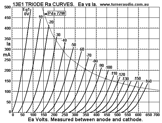
Fig 19 shows the crowding together of Ra curves above 350Vdc. For
a CCS load = 100mA,
and a Q point at 350Vdc, for Vg1 swing +/- 80Vpk, Va swing =
-320Vpk, + 277Vpk, 2H = 6.4%.
This is 3 times higher than for many other real triodes or
tetrodes / pentodes strapped as
triodes. Average µ g1 = 3.54, and Ra at 350V x 100mA = 450r, gmg1
= 7.87mA/V.
At Ea = Eg2 = 345V x 200mA, Eg1 = -70Vdc, µ = 4.0, Ra = 300r, gmg1
= 13.3mA/V.
I have met people who have used 13E1 in OTL amps because they have
a high peak current
ability of maybe 1A. A PP series pair in class B could produce
1Apk for 8W to 16r0 speaker.
The linearity will be very bad and 40dB of NFB is needed. But the
triode idle condition could
be +175V x 50mAdc, Idle Pda = 18W, two tubes, and this rises to
60W when 8W of audio Po
is produced. To understand the foolishness of OTL amps, read OTL-amps-pros-cons.html
Fig 20. 13E1 triode, RLa loads for 2 different Q points.
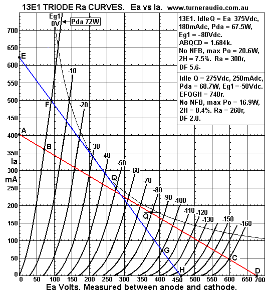
Fig 20 shows Q points, both at Pda+g2 = 68W approx. Consider ABQCD
load with
Q point = 375V x 180mA. I tried this in 1997. I remember the THD
was high, and Pda could
not be much above 72W for triode or UL or else anode glowed red.
UL with g2 tap at 66%
did work best to give the most class A1 Po and give THD without
much of the high number H
which occurs with pure beam tetrode with Eg2 at same Ea of
+375Vdc. UL Ra was about 600r,
and there was more class A1 than triode, about 25W, because the Va
could swing closer to
points A and D. In triode, it may be possible to push g1 to +10V
and use GNFB to get slightly
wider Va swing and maybe get higher Po. But without slight class
A2 operation, and only 12dB
GNFB, and with driver tube making 2% 2H at +/-80Vpk expect THD =
1.4%. The first 13E1 UL
amp I made is discussed at MonoblocSE25.html
I found it better to use this tube in beam tetrode mode with CFB,
see monobloc-se32-13e1-cfb-2012version.html
---------------------------------------------------------------------------------------------------------------------
General Summary.
Single triodes make good amplifiers, but they cannot do all that
is wanted. I have seen
people build 1.5W amps using a tube that was discussed at a
website and they try to
build a pair of horn loaded speakers with a pair of Lowther "full
range" drivers.
They battle for 3 months with the woodwork with a terrible tool
kit, and then they find
the sound is just dreadful. The horn loaded design just does not
do what the online
promoter said it would, and bass is non existent. So they end up
with expensive fire
wood, and the power amp could only ever be a headphone amp, but
only if they know
how to make one of those properly.
Most of my listening is done with a 5W SET amp in a kitchen radio,
using a 1953
300mm driver in a reflex bass box, with a dome tweeter, all
carefully equalized, and with
GNFB in the amp. See details at Kitchen-AM-Radio-2015.html
But many ppl want to fill a lounge room with much louder sound
equal to being at a
live concert performance with 50 musicians or singers only 5
meters away. If they have
average modern speakers with lower sensitivity than what was
available in 1953, they
need much more than a 5W amp. More like 300W amps are needed to
cover natural dynamic
music range without the limiting of peak power so typical of
recorded music. For those into
heavy rock and roll, I suggest a solid solid state amp with at
least 100W per channel.
Most rock and pop music is hugely "processed" to make it sound
better than any of the
performers could achieve without electronics and digital effects
added. Use of expensive
triode amps won't make over processed recordings of puerile
screaming head basher "music"
sound any better.
Hi-fi is preserving the acoustic music meant to be heard in front
of audiences with no
electronic enhancement using overloaded devices to add harmonic
content. Most people
will not enjoy having 50 performers crammed into their little
homes, and they like to sit well
away from 50 performers on a stage in a big hall. The audience
will cope enjoyably with all
musicians busy or just one violinist. There is no law against use
of electronics on stage or in
a recording studio. Alice Giles is a fabulous harp player, and I
heard her on stage once using
a harp with a pile of electronics beside her, including a
sub-woofer - and the result was
fabulously musical, but never tricked up and fake. This kind of
electronic use is very different
to a punk band in a hotel using all amps turned up full to make
the most deafening
garbological noise ever to have been heard.
SE amps sometimes do provide "color" for the sound heard, and
change of brands of tubes
used may change the color. This may lead to endless tube and amp
changes to find the
ultimate experience. It is audio promiscuity. I have seen rational
men change amps and
speakers every year and sometimes every 6 months. By comparison,
I've been happy with a
kitchen radio, mono sound, and ABC Classic FM giving me access to
better music that I could
ever choose elsewhere for myself. The FM hifi standard of 20Hz to
15kHz has always been
quite acceptable for myself and millions of others.
The LP can often sound better than the very best digital
recording. Hi-fi came into being in
about 1949 with invention of LP and good moving coil pickups. Much
music was recorded using
tubes in tape recorders, and LPs were cut using tube amps to power
a cutting head.
Tape recording excelled and home hi-fi often allowed closer
connection to performers than if
people attended a concert. The best of recordings made with all
analog gear was often better
than much made later using digital methods. I am a bit stuck in
the past, and I have never ever
needed the high power and flashy expensive hyped up expensive
stuff pushed at us at a shop
called Consumania. I learnt how to make amplifiers far better than
anything I could buy, and if
I wanted something different, I just went to my shed and made it.
Fortunately, there were enough
parts available to avoid making tubes, capacitors, resistors,
switches, tubes and solid state
devices.
Whatever color is added by the tubes is usually acceptable; the
range of differences heard
are rather like the range of flavours we may find in 6 bottles of
Shiraz from 6 different wine
makers. All are drinkable, perhaps some different / better / worse
than one another.
Of course it is well known that a group of wine experts can be
fooled when a glass is filled
from a bottle costing $10 and told it came from a hallowed old
vineyard, and had cost $3,000.
They'll only praise the plonk if they know its expensive.
I never drink now, but when I did, each glass had its delights,
but the alcohol was the key to
delights. The music itself should be like the alcohol, and amps
may make it taste slightly different.
Unlike alcohol, you can drink 6 bottles of Mozart a day without
ill effects, and generally, triodes
serve it very nicely.
I cannot dictate to anyone what kind of amp they should have, but
I would always suggest
to anyone they could try some tubes......
In an earlier edition of this page, I showed methods of testing
IMD of SE triodes.
This info has been moved to thd-measurement.html
You are at
LOAD MATCHING 1, SE
TRIODES
To
LOAD MATCHING
2, SE BEAM TETRODES and PENTODES
LOAD MATCHING 3, PP
TRIODES
LOAD MATCHING
4A, PP TETRODES and PENTODES
LOAD MATCHING
4B, PP TETRODES and PENTODES
LOAD MATCHING
4C, PP TETRODES and PENTODES
LOAD MATCHING 5
To
education+diy.html
To index page


