LOAD MATCHING 4B, PP BEAM TETRODES or PENTODES.

Last edited 2017. This page 4B follows 4A.
This page 4B precedes 4C to keep page size low.

Content :-
Table 5. Class A1 RLa-a loads for 2 x 6550 or KT88, pure beam tetrode,
or with CFB, with fixed Eg2.
Table 6. Class A1 RLa-a loads for KT120.
Table 7. Class A RLa-a loads for KT66, EL34, 6CA7, 6L6GC.
Comments on operations.
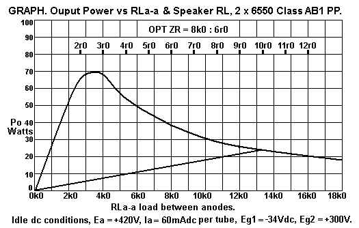
Fig 7. Graph for Po vs RLa-a, 2 x 6550 PP, Ea +420V, Eg2 = +300V.
Comment about supporting experience underpinning loading ideas etc.
Anode heat dissipation. Class A and AB.
Amp output resistance calculations beam tetrode, UL.
Beam tetrode background.
--------------------------------------------------------------------------------------------------------------------------------
Table 5. Class A1 RLa-a loads for 2 x 6550 or KT88, pure beam tetrode, or with CFB, with fixed Eg2.
Class A1
PP tubes
Idle Pda
+ Pdg2 =
0.7 x rated
max Pda
1 tube,
Watts
Pda
only,
1 tube
Watts
Idle Ea,
+Vdc
Idle Iadc,
 mAdc
Eg2
+Vdc
min'm
Ig2
mAdc

RLa-a =
1.9 x
Ea / Iadc
ohms r
Class A1
Max Po
at anodes,
Watts,
THD 1%,
Class A
Anode
max
efficiency
%
2 x 6550
29.4W
27.4W
300V
91mA
250V
8mA
6,333r
25.6W
47%
2 x 6550
29.4W 27.2W
325V
83mA
275V
8mA
7,439r
25.6W
47%
2 x 6550 29.4W 27.0W
350V
77mA
300V
8mA
8,750r
25.3W 47%
2 x 6550 29.4W 27.0W
375V
72mA
300V
8mA
10,178r
25.0W 46%
2 x 6550 29.4W 27.0W
400V
66mA
300V
8mA
11,515r
25.0W 46%
2 x 6550 29.4W 27.0W
433V
61mA
325V
7mA
13,487r
25.1W 46%
2 x 6550
29.4W
27.0W
467V
57mA
325V
6mA
15,566r
25.3W 46%
2 x 6550
29.4W 27.0W
500V
54mA
350V
6mA
18,270r 24.7W
45%
Table 5 is a guide to approximate Po outcomes for 6550 or KT88 with various Ea and Ia for a
constant idle Pda+Pdg2 = 29.4W.
For example, for Ea = +400V, Iadc = 66mAdc, Pda = 26.4W, Eg2 = 300V, Ig2 = 8mAdc, Pdg2 = 2.4W.
Total Pda+Pdg2 = 28.8W, which is close but < 29.4W, so is OK. The PP class A anode Po = 25.3W
giving anode efficiency = 47% approx and which depends on low THD with 20dB NFB. This is close to
the maximum possible class A efficiency of 50% where diode line resistance = 0.0r for a perfect tube.
Perfect tubes do not exist.  
The use of a typical generic OPT with winding losses of 10% will reduce Po to 22.86W, and then class A
efficiency = 42.3% which is a maximum efficiency figure often quoted in text books.

The screen Idc is approximate, and Rd diode line resistance may be between 125r and 300r depending on
mode of operation.
I have assumed it to be 200r here for pure beam tetrode with fixed Eg2. Use of CFB windings allows Eg2
to be lower than Ea, so the above figures are correct for CFB. For UL with g2 taps between 30% and 55%,
assume Rd = 300r. The above is a guide only.

The most accurate calculation of pure class A RLa-a = 2 x [ Ea - ( 2 x Iadc x Rd ) ] / Iadc, where the
diode line Rd value is known, and Iadc is the dc idle Ia in ONE of the output tubes. 
The real value of Rd in any of many modes of pure tetrode, pentode or UL or CFB is very difficult to confirm
by the DIY person, but should be low enough so that Rd value is of little concern. The data graphs from past
give approximate Rd value. The Ea and Eg2 and Eg1 can be varied experimentally for the best wanted
outcome without filling a room with smoke.

The simplest formula for beam tetrode and pentode PP class A RLa-a has RLa-a = 1.8 x Ea / Iadc,
with Iadc being for one tube, with the same Iadc in each PP tube. 

All Po mentioned here is assumed to be at the anodes, ie, at the input to the OPT primary. OPT winding losses
can be between 2% and 25%. The best OPTs have Rw < 5% for where the RLa-a is lowest for high class AB Po.
If the secondary load is increased to say 4 times the RLa-a value for class AB, the class A losses may reduce to
less than 2%.

I have repaired or restored many old amps where an OPT may have Rw = 10% with the high pure class A RLa-a.
If the RLa-a is halved for more class AB1 with less initial class A and, class AB losses are more than doubled,
can be 28%, especially if some secondary windings cannot be included for the desired load match. Quad-II OPTs
were a classic example of a high loss OPT when using 4r0 connected the OPT when it is strapped for its lowest
recommended strapping for 8r0. The Quad-II OPT does have a tap where 4r0 can be connected but only 1/2 the
secondary turns are used and winding losses are lamentably high.

There are few benefits of having Ea more than +400V for all large octal based tubes for class A Po. The RLa-a
becomes too high and it becomes impossible to find a suitable OPT, and more difficult to wind one.
The same attitude is valid for all output tubes. For class A Po you do not need the highest Ea which can be used
for the tube. High Ea should be reserved for high class AB Po with low amount of class A.

Notice that for Ea = +500V, the class A RLa-a = 18k3, for 2 x 6550. The OPT will have a primary of many turns
of very fine wire with high Rw which would fuse all too easily when Idc went high in a faulty 6550. However,
with a well designed OPT with a large core the 18k3 : 4r0, 8r0, 16r0 can be achieved. The linearity will not be
better than if the Ea = +350V and OPT is 8k7 : 4r0, 8r0, 16r0. The 5050 I first built in 1998 demonstrated
that using Ea at +500Vdc was no barrier to excellent hi-fi.

Table 6. Class A1 RLa-a loads for KT120.
Class A1
tubes
Idle Pda +
Pdg2 =
0.7 x rated
max Pda
1 tube,
Watts
Pda
1 tube
only,

Idle Ea
+Vdc
Idle Iadc
mAdc
Eg2
+Vdc
min'm
Ig2
mAdc
RLa-a =
1.9 x
Ea / Iadc
ohms r
Class A1
Max Po at
anodes,
THD 1%,
Watts
Class A1
Anode
max
efficiency,
%
2 x KT120 40.0W
36.9W
300V
123mA
250V
10mA
4,634r
35.0W
47%
2 x KT120 40.0W 36.7W 325V
113mA
225V
10mA
5,465r
34.8W 47%
2 x KT120 40.0W 36.4W
350V
104mA
250V
10mA
6,394r
34.6W 47%
2 x KT120 40.0W 36.4W
375V
97mA
275V
10mA
7,345r
34.5W 47%
2 x KT120 40.0W 36.0W
400V
90mA
300V
10mA
8,444r
34.2W 47%
2 x KT120 40.0W 35.9W
433V
83mA
325V
9mA
9,912r
34.1W 47%
2 x KT120 40.0W  35.9W
467V
77mA
350V
9mA
11,523r
34.1W 47%
2 x KT120 40.0W 36.0W
500V
72mA
350V
8mA
13,194r 34.2W 47%
Table 6 is for pure class A1 with 2 x KT120 to give available Po = about 34W at anodes or about
31W at OPT sec. One may argue this is more than anyone will need considering average Po levels
remain the same 1W for each speaker of a pair regardless of what amp is used.

Therefore the KT120 may be run at the same Ea and Ia levels at 6550 or KT88, ie, idle Pda = 29W,
which is less than 0.5 x Pda max for KT120, so they should give a longer life than 6550 or KT88. 

Table 7. Class A RLa-a loads for KT66, EL34, 6CA7, 6L6GC.
Class A1
PP tubes
KT66 or
EL34 or
6AC7 or
6L6GC
Idle Pda
+ Pdg2 =
0.7 x rated
max Pda
1 tube,
Watts
Pda
only,
1 tube
Watts
Idle Ea,
+Vdc
Idle Iadc,
 mAdc
Eg2
+Vdc
min'm
Ig2
mAdc

RLa-a =
1.9 x
Ea / Iadc
ohms r
Class A1
Max Po
at anodes,
Watts,
THD 1%,
Class A
Anode
max
efficiency
%
2 x KT66
20.0W
18.1W
275V
66mA
250V
7mA
7,916r
17.2W
46%
2 x KT66 20.0W
18.0W
300V
60mA
250V
6mA
9,500r
17.1W
47%
2 x KT66
20.0W 17.9W
325V
55mA
275V
6mA
11,227r
17.0W
47%
2 x KT66 20.0W 17.9W
350V
51mA
300V
6mA
13,039r
17.0W 47%
2 x KT66 20.0W 17.7W
375V
47mA
300V
6mA
15,159r
16.7W 47%
2 x KT66 20.0W 17.6W
400V
44mA
300V
6mA
17,272r
16.7W 47%
2 x KT66 20.0W 17.7W
433V
41mA
325V
5mA
20,065r
16.8W 47%
2 x KT66
20.0W
17.3W
467V
37mA
325V
5mA
23,981r
16.4W 47%
2 x KT66
20.0W 17.5W
500V
35mA
325V
5mA
27,143r 16.6W
47%
A pair of KT66, EL34, 6CA7, 6L6GC, 5881 may be used with above Ea / Ia conditions.
Notice that a pair of these tubes give about 1/2 the class A Po as a pair of KT120. So you could
have a quad of KT66 or EL34 etc, and get the same class A as a pair of KT120.
The quad of medium size octal tubes may be a cheaper solution and a technically better because the
gm of 2 x KT66 or EL34 is higher than for 1 x KT120 where the total Pda is 40W. I have built
100W amps using 6 x EL34, and was very easily able to get 100W AB and a high amount of initial
class A Po, and sound was creamy, detailed, effortless, and gutsy when required.
See 100w-monobloc2-2004.html .
From the above Table 3, use of 6 x EL34 can give 54W of pure class A.

Notice that for Ea 400V, 4 x KT66 would have OPT primary RLa-a = 8k6. The single pair of
KT120 requires RLa-a = 8k4 for the same Ea of 400V. The RLa-a are effectively the same, so
that the 4 x KT66 etc is an exact replacement for 2 x KT120.

The the best class A action for PP KT66 or EL34 etc is for Ea + Ia conditions are 350V x 51mAdc
to 400V x 44mAdc, with OPTs with primary RLa-a between 13k0 and 17k3.

The tubes in all class A conditions in tables above will tolerate reduction of 50% of RLa-a for
class AB operation.

For example, consider 2 x KT66 with Ea 400V and Ia 44mAdc. Class A RL a-a = 17k3.
If the RLa-a was reduced by 50% the RLa-a = 8k6, and initial class A Po = 8.3W, and max
class AB Po will rise to about 31W. For most ppl, the result is excellent hi-fi where the OPT has
50% UL screen taps or if there is 20% of primary turns devoted to local cathode FB.

There is no strict rule to have Eg2 lower than Ea where Ea is less than Eg2 maximum rating.
But for CFB use, I found less THD where Eg2 was lower than Ea. The lower Eg2 means Eg1 bias
is lower so that cathode biasing networks have a lower Rk and Ek is less likely to move when class
AB action is inevitably demanded when someone connects 4r0 to 8r0 outlet, and forces the amp
to work in class AB at high levels.

The screen Eg2 supply for all beam tetrodes and pentodes must never ever exceed Ea under any
circumstances. 6CM5, 6DQ6 and 13E1 can have Eg2 much less than Ea.

Straight lines to describe resistance loads are not always straight in the real world.
In any SE amp, the load line is always really straight, ie, the load resistance value remains constant
for all parts of any wave form. The exception to this fixed concept is where there is reactive L or C
connected in parallel or is series with the resistance load. In SE tube amps, the primary inductance
Lp may have a value where the parallel reactance XLp in ohms equals the RLa at say 20Hz.
If the RL-a was 7k0, and XLp was also 7k0 at 20Hz, the resulting impedance of the parallel load
network Lp // RLa would be about 5k0. If the tube is a beam tetrode with high Ra > 35k0, the load
remains 5k0, and if you display the transfer function on a CRO of Va versus Vg1, you will find you
get an ellipse, not a straight line, and that is because of phase shift caused by the Lp.

I have just confused everyone. But all this appears true when you graduate from dumb DIYer to
knowledgeable amp maker. And even with no Lp shunting RLa, a pure resistance RLa gives a bent line,
so why isn't that straight? It is because of the THD, ie, the tube does not have a fixed ratio for
Va change / Vg change. But if the tube was perfectly linear, or a huge amount of NFB is used, then the
transfer line is straight, and it represents the change of Ea and Ia along a straight line resistance load.

In PP amps, and for the first couple of watts, each tube works just like an SE tube with a class A
RLa = RLa-a / 2, and each tube is fairly linear. Each tube has Va and Ia change that is opposite phase.
But as the level is raised the each tube begins to cut off its Ia with decreasing gm function on negative
going Vg peaks, and increase its Ia with increasing gm on positive going Vg peaks.

The combination of both oppositely phased Va applied to each end of a center tapped OPT primary
means that the resulting Vo from a secondary winding has virtually none of the 2H of each tube included
in its output. The 2H produced by each tube has the same phase, and is applied in common mode to
each end of the OPT primary so no 2H current flows in the primary winding so there is no 2H in Vo
at secondary. The amp's NFB is taken from the secondary, so no correction of 2H is applied to either
grid of output tubes. The output tubes are therefore allowed to work quite non linearly to produce their
linear class A or class AB Po.

While in the initial class A working, each output tube's current delivery to the load is summed with the
other tubes, and one tube's class A RLa A load changes the other tubes RLa load. This means the
real load line for RLa is a slightly curved. We can safely ignore this in our load calculations, lest we
become totally lost in mathematics and curvaceous graphs which would not lead us to good predictions
of circuit function.

In class AB, each tube takes turns to have Ia cut off completely on negative going Vg input. The cut off
behaviour is non linear. When cut off occurs in one tube, the other tube keeps going with increasing gm,
and its load becomes RLa-a / 4, the class B RLa. So there is a big change of load between RLa-a / 2 to
RLa-a / 4. The AB load lines indicate the load change is an abrupt change of angle of the two load values
 drawn as straight lines. In fact, the AB loading change is a curved transition. Because of the curved nature
of class AB load change, the H produced are mainly 3H. The sharper the load change, the greater the
variety of H produced.

The harmonic distortion produced by load change is often called crossover distortion, the usual term for
output tubes set up with very little idle current, and giving negligible class A Po, and a high amount of class
AB which in fact is close to being pure class B where idle Idc is zero mA.

Triode PP class AB amps produce the least AB transition harmonics, mainly 3H, and usually the sound is
fine if enough GNFB is used. I found local output stage CFB also give excellent transition from A to AB
even with low idle Iadc as little as 30mAdc in 6550. Tubes have more gradual cut off behaviour than solid
state devices which is nearly always set up in class AB with very low idle current and making less than 0.5W
of initial class, hence the need for at least 50dB of GNFB.
-----------------------------------------------------------------------------------------------------------
Fig 7. Graph for Po vs RLa-a, 2 x 6550 PP, Ea +420V, Eg2 = +300V.
18-graph-po-vs-rl-pp6550-beamtetrode.gif
Fig 7 graph shows the power output from 2 x 6550 class AB in Fig 2 and Fig 3 above.
I show use of OPT with 8k0 : 6r0 load ratio. OPTs should have variable load outputs of 4r0, 8r0, 16r0,
but in this case show just one output load = 6r0.

With only one 6r0 output, use of 16r0 speakers will give RLa-a = 21k3, which cannot be plotted
on the right side of graph but 16r0 would give about 15W of pure class A and if you have an old pair
of sensitive 16r0 speakers, the 15W will sound fine, ( although a teenage son who prefers Rock-Grunge
Concertos at 250dB SPL may disagree ).

Few people have 16r0 speakers. With only one output of 6r0, the ideal impedance for a speaker is 6r0
where RLa-a = 8k0 and the tubes make the first 15W in class A with 38W total for class AB. Speakers
with Z from 5r0 to 10r0 will be OK. Most speakers nominally "8r0" will have a Z range between 5r0 and
30r0.

The maximum possible anode Po of the two 6550 is shown at 70W at RLa-a = 3k5. We may assume
that a good OPT has total winding losses of 5% at 8k0 : 6r0. The OPT winding losses could be expected
to be 11% when loaded by RLa-a = 3k5 for maximum Po, so at a speaker load of 2r7, there will be
62W class AB, with only 6W of pure class A.

Some amp manufacturers would advertise an amp with 2 x 6550 or KT88 as being capable of 70W,
with OPT ZR = 3k5 : 4r0 or 8r0. This means most speakers cannot you much class A; the tubes are
always working in the region for high class AB with little initial class A. Being able to brag about Po
= 70W does not improve your hi-fi experience.

Manufacturers and their promoters should arrange their amps to have the absolute real maximum Po
of 62W only possible when the load value is 1/2 the nominal speaker load when it is connected to a
terminal labelled with that load.

An OPT of 3k5 : 4r0 and 8r0 is no good for hi-fi. The OPT should be 8k0 : 4r0 and 8r0. This will give
35W with either 4r0 or 8r0 speakers, with initial class A = 15W for either speaker value.
If say "8r0" speakers be connected to 4r0 output terminal, the RLa-a becomes 16k0, and Po = 20W
and it is all class A with THD halved and damping factor doubled. If the 20W is enough Po to produce
all the volume needed without clipping then the sound is better. The high 60W Po capability is saved for
where a 4r0 or 8r0 speaker has impedance dips to 1/2 the the nominal value - something I often
measured in real world speakers.

In fact it is two amps within one, and paradoxical. Manufacturers are quick to rave about their 57W
class AB amps being much better than a weak sickly class A amp capable of only 28W..

But the marketing of anything *always* severely distorts the truth.

Many speakers are rated rated for 88dB SPL per Watt at one metre. Sometimes this rating for 1W is
stated for 2.83Vrms of amp output Vac. Beware, because the maker is avoiding to mention the load
value. If the speakers are 4r0, the Po = 2W, not 1W as is the case for 8r0, so the real rated SPL
would be only 85dB/W/M.

But let us assume your pair of speakers have sensitivity = 88dB/W/M. Total Po to both speakers
= 1W and each amp for 2 channels makes 0.5W for 85dB SPL from each speaker which sums to 88dB.
For a total 98dB you need 10W from both amps, and for 108dB you need 100W, and so you need 50W
per channel. The pair of 6550 or KT88 will give you the 50W if you have the load matching fairly correct.

I went to a recent 2017 Baroque music concert in a small Anglican Church at Cook in ACT, 180 ppl
were seated around 30 musicians all playing stringed instruments with no amplifiers or speakers.
The music by a range of Baroque composers, Vivaldi, Correlli, Handel was just at the right level.
To reproduce the magic everyone heard from a pair of speakers at home would have needed about 50W
from two amps to two full range speakers. I have made speakers rated for 88dB/W/M, and found sound
with 2 x 6550 per channel works well.

If the amplifiers have 4 x 6550 per channel, you can get 100W per channel, and this raises the SPL
to a possible 111dB, only +3dB more than using 2 x 6550 per channel. The extra class AB1 potential
for more tubes is a very minor benefit.

A long time ago in early 2000, I attended at least three Sunday meetings of the Audio Society of NSW
at Sydney. I demonstrated 3 different types of amplifiers shown at my website using my amps and my
own speakers or Duntech Statesman speakers. On each occasion there were 30 men gathered in an old
library venue with large enough and good acoustics. The 8585 with 4 x 6550 per channel probably
sounded best, but they were quite well impressed by a sample 5050 with 2 x 6550 per channel.
I also demonstrated a pair of 25W SEUL amps, each with a single 13E1 tube. The audiophiles were
there for hi-fi, and never to have their ears bashed to bits with high Po!

Nothing has much changed in 60 years about preferred SPLs for general hi-fi listening levels and in RDH4
they say men prefer an average level of 88dB while women prefer 84dB. These may be average levels
found in an ideal seat in front of a 40 piece orchestra. I have confirmed these SPLs by using a sound level
meter, The likely difference between the real live concert in a large venue and a hi-fi system at home will be
the dynamic range. In the live venue, there is no limiting of transients and no use of compression which is
often applied to music recordings to limit the dynamic range. The concert hall freshness and sparkle is as
pure an experience as it ever can be. Recordings sometimes lose the dynamic range.  

We do have to draw a line somewhere with power. I once re-engineered a Leak 20 for a customer who
wanted to hear great things from tubes through his large floor standing Duntech Sovereign speakers.
These were similar to Acoustic Research AR9 but the Duntechs were made to much higher quality.
The Duntech had ZL from 3r0 to 4r5 and 87dB/W/M sensitivity. The Leak 20 gave a pretty good
12W AB per channel from a pair of EL84, and maybe 8W of pure class A. The Leak 20 has adjustable
output load matching and can be set for 4r0. But they lacked the power to drive the Duntech properly
with low THD. But in 1960 many speakers had sensitivity at 96dB/W/M. The Leak 20 would sound
much happier driving a pair of 15" Tannoy dual concentric drivers in 170 Litre bass reflex boxes.
I know someone with such speakers and spent an evening listening and he used 10W SE amps each
with 1 x 300B made by Allessa Vaic a long time ago. Sound was terrific. The load matching was just fine. 

If you want busy sound from Bob Marley etc with insensitive speakers, just use more tubes in each channel.
There is no substitute for having more glassware unless you insist on a pair of 845 or 13E1 in PP AB1 -
these are really something to behold.

The effect of NFB on output resistance can be explained similarly as I explain in my page on
Load matching 2 for load matching to Single ended beam tetrodes.
------------------------------------------------------------------------------------------------------------
ANODE HEAT DISSIPATION.

PP Class A operation.

The RLa-a for maximum pure class operation is approximately calculated as RLa-a = 1.8 x Ea / Iadc where
1.8 is a constant and Iadc is the idle Ia for each tube.

For a pair of 6550 in tetrode mode with idle Ea = 400V, Ia = 73mAdc, RLa-a = 1.8 x 400V / 0.073A = 9,863r.
Maximum class A Po = 0.5 x Iadc squared x RLa-a = 0.5 x 0.073 x 0.073 x 9,863r = 26.2W at clipping, with a
sine wave at say 400Hz.
Total Pda at idle, 2 x 6550 = 2 x Ea x Ia = 2 x 400 x 0.73 = 58.4W. This means the DC power to tube anode
at idle = 58.4W, and for all levels of class A Po up to clipping the DC power from PSU does not change.
Therefore as the level of class A Po increases, the heat dissipated by radiation from anodes decreases to a
minimum = DC power input - Max class A Po = 58.4W - 26.2W = 32.2W. This is evenly shared for the
2 x 6550, so each one has Pda = 16.1W at maximum class A Po.

So the harder you drive a pure class A amp, the cooler it runs. The tube is hottest at idle and when set up for
maximum pure class A.

But usually the average power in music signal is < 1W, so the cooling effect of higher power is negligible, so
Pda for class A remains fairly constant and the 6550 are at 29.2W each, and Pda per tube = idle Ea x Iadc.

PP class AB operation.

The anode dissipation in class AB amps may vary considerably depending on the RL and idle bias currents.
The Pda max for a class AB amp will always be highest when RLa-a is at a minimum value, ie, when RLa
is also at a minimum value.
Consider Fig 6 above for 2 x 6550 with Ea = +600V, Ia = 40mAdc, minimum RLa-a = 5,333r, and with
BRLa as WVYU = 1,333r. Va-a maximum = 775Vrms and Max AB Po = 112.6W.
 
From Fig 6 load line for 1,333r, Iapk maximum at point V = 0.41Amps. The Vapk swing at each anode
= 548Vpk.

The maximum Iapk is more than 10 times the idle Iadc.

Now the Pda at audio Po > 1/2 maximum possible AB Po is approximately equal to what is produced
in a theoretical pure class B amplifier where the Ia current waves in each tube are like the positive 1/2 of a
sine wave.

Power drawn from PSU, P-psu, at more than 1/2 maximum AB Po may be calculated as for a pure
class B amp as :-
P-psu = Ea x average Peak Ia = Ea x Peak Ia x 0.636.
P-psu also is = Ea x 1.8 x Va-a / RLa-a.

Total Pda, both tubes = Ppsu - Po.
Therefore Total Pda = [ ( Ea x 1.8 x Va-a ) / RLa-a ] - [ (Va-a squared / RLa-a ) ]
= { Va-a x [ ( 1.8 x Ea ) - Va-a ] } / RLa-a.

In this example, Pda = { 775Vrms x [ ( 1.8 x 600Vdc ) - 775Vrms ] } / 5,333r = 44.3W.
Pda per tube = total Pda / 2 = 44.3W / 2 = 22.15W. This is about half the rated max Pda for 6550 of 42W,
so the tubes do not overheat at the clipping level with RLa-a = 5,333r.

The class AB efficiency = 100% x Po / ( Po + Pda ) = 100% x 112.6 / ( 112.6W + 44.3W ) = 71%, which
is quite good because the maximum possible PP efficiency = 78% in a perfect amplifier for perfect class B
operation.

What would happen the RLa-a was halved to 2,666r for the pair of the pair of 6550 in Fig 6?
The B RLa = 666r, if you plotted the loadlines the max Iapk = 455mA, and this is limited by the Ra curve for
Eg1 = 0.0V, and Eg2 = +300Vdc. If Eg2 was +400Vdc, the Ia pk could swing much higher and higher Po
would be possible, and maybe Pda would also rise.
The Va-a for 2,666r = 467Vrms and the Po = 81.8W.

Total Pda = { 467Vrms x [ ( 1.8 x 600Vdc ) - 467Vrms ] } / 2.666r = 107.4W.
The Pda per tube = 53.7W, considerably exceeding the Max Pda for 6550 = 42W.

Therefore RLa-a = 2k7 is too low, gives less max Po than for 5k3, gives twice the THD, and half the
damping factor and leads to short tube life ifthe tubes are always driven hard, as they may be in a guitar
amp.
It is all too easy for someone to plug a 4r0 speaker to an amp terminal labeled for 8r0, and then overdrive
the amp, which makes the output wave form become a square wave. Such over driven tubes can occur if
speaker leads or speaker has a short circuit, and even low level signals with a shorted pair of output
terminals will easily produce overheated tubes without causing fuses to blow. Fuses may blow when tubes
become internally short circuited due to warping of metal electrodes due to excessive temperatures.
To avoid the damage to tubes, OPTs, PTs, filter chokes et all, active protection must be used.
------------------------------------------------------------------------------------------------------
Amp Output Resistance, Ro, aka output impedance.
PP beam tetrode or pentode power amps have very high Ro unless a lot of NFB is used. For a typical
pair of 6550 or KT88 in pure tetrode mode, the dynamic resistance measured between anodes at idle
could be 65k, and if the OPT is 8k0 : 6r0, then
Ro measured at secondary output = Ra-a x Sec RL / Pri RLa-a
= 65,000r x 6r / 8,000r = 49r, and the damping factor = Sec RL / Ro = 6r / 49r = 0.122.
This DF is way too low, and we would like DF to be about 10, where Ro would be at least 0.6r.
The only way to reduce Ro is to apply GNFB, or else strap say 6r8 x 20W across the output.
The GNFB is the best way because it gives a huge reduction of Ro. The 6r8 would waste 1/2 the Po
of the amp and reduce the RL to about 3r0, and give Rout = about 6r0 for DF = about 1.0, which is not
good enough plus the THD is worse, so strapping R across outputs is a very poor solution.
However, if the 6r8 has a 0.22uF cap in series, the amp is not loaded within the audio band but above
50kHz the 6r8 +0.22uF becomes a load of 6r8 by 200kHz, and this loads the amp with resistance
at HF which aids stability. That is an issue dealt with elsewhere.

Let us assume class A gain of 6550 at low level is where highest gain occurs, where RLa-a = 8k0,
and class A gain for RLa = 4k0 is approx gm g1 x 4,000 = 0.006 x 4,000r = 24x.
The OPT of 8k0 : 6r0 has TR = 36.5, so Va-a = 36.5Vrms with 1Vrms at Vo. If 6550 gain = 24,
Vg-g input = 36.5Vrms / 24 = 1.52Vrms.
If there is an LTP driver using a 6GG7 with total differential gain of 8, and an SE input 6CG7 with
gain = 16, then gain of input + driver = 8 x 16 = 128. V1 Vg-k of V1 will be 1.52Vrms / 128
= 0.012Vrms.
This all means than without any GNFB we need 0.012Vrms to make 1.0Vrms at Vo,
so "open loop gain", ie, overall gain A without NFB = 1Vrms / 0.012 = 83. But the amp can make
38W for 6r0, or 15Vrms at output. The output tube gain high AB Po may reduce from 24 to say 20,
so OLG at high Po = 69. So the V1 Vg-k input for clipping with no NFB would be 15Vrms / 69
= 0.217Vrms.

When 20dB GNFB is used, the Vg-0V will increase to 2.2Vrms, and there will be a fraction of the
output Vo applied to V1 cathode = Wanted Vin - Vg-k for max Po = 2.2Vrms - 0.217Vrms = 1.98Vrms,
and the fraction ß fed back at V1 = 1.98Vrms / 15Vrms = 0.132.
The closed loop gain with GNFB = 15.0Vrms / 2.2Vrms = 6.82.

Those not use to the rapid fire calculation of working out all Vac and NFB need to build a lot of amps
to get practice.

The use of the GNFB reduces overall gain to become "closed loop gain", CLG, ie, gain with GNFB,
and here it is 10.0.
The gain reduction factor = gain A' with NFB / gain A without NFB = 6.82 / 69 = 10.0 / 69 = 0.1
= 20dB of NFB.
The THD will be reduced by same factor.

Calculate expected Rout at Sec of OPT at low level

ß = 0.132.
Ra-a = 65,000r
OPT ZR = 8,000r / 6r0 = 1,333.
OPT TR = 36.5.
µ of output 6550 = gm g1 x Ra of one tube = 0.006A/V x 32k5 = 195. Note, gm g1 is lower than data
with idle Ia = 60mAdc.
Gain A" of SE input and LTP driver = 128.
Allow OPT at Pri input = 10% of RLa-a = 800r.

Rout of the amp with FB applied = ( Ra-a + total Rw OPT ) / ( ZR x [ 1 + ( A" x { µ / TR } x ß ) ] ).
The figure 1 is a constant for all equations.
Notice that the gain of output tubes is used for Rout calculations, but the tube µ is needed.

Rout = ( 65,000r + 800r ) / ( 1,333 x [ 1 + ( 128 x { 195 / 36.5 } x 0.132 ) ] )
= 65,800r / ( 1,333 x 90.3 ) = 0.55r.

The damping factor = Sec RL / Amp Ro = 6r0 / 0.55r = 10.9 > 10 = OK.
In the case UL connected pair of 6550 with UL taps at 50%, each 6550 has Ra = 2,500,
so Ra-a = 5k0.
The µ for UL = gm g1 x UL Ra = 0.006 x 2,500 = 15.
50% UL Rout = Rout = ( 5,000 + 800r ) / ( 1,333 x [ 1 + ( 128 x { 15 / 36.5 } x 0.132 ) ] )
= 5,800r / ( 1,333 x 7.94 ) = 0.55r.

Damping factor for 50% UL, with the same value for ß = 6r0 / 0.55r = 10.9, and the same as
for pure beam tetrode.
The 50% UL connection will much reduce Ra-a and reduce odd number HD products of 6550.
Therefore in practice the UL should give lower number of H products. The gain of 6550 with 50%
UL will reduce from 24 in pure tetrode to about 9.3.
Therefore the OLG for calculation of applied GNFB will have OLG at 32, and the amount of GNFB
is thus less because of the lower gain of 6550. So applied GNFB with 50% UL will effectively
become about 14dB, for the same value of ß = 0.132.
The Vin will not be much higher with the change to 50% UL.

Larger reductions of effective Ra-a in the OP stage are possible with the Acoustical connection.
Even 10% CFB as used in Quad-II reduces Ra-a of KT66 from 76k0 to the same as triodes,
approximately 3k2, a reduction of more than x 1/20. I prefer the Acoustical with CFB option,
and when using about 20% of the primary for CFB, the drive voltage to an output grid is raised to
about 75 Vrms, or about 7 times the pure beam tetrode drive voltage so then the driver amp needs
to have more idle current and low distortion ability. But I think the end result sounds better with the
CFB and a small amount of Global NFB.

The previous samples are approximate calculations of what to expect when you build and
measure an amp. For more about NFB within triodes, and theory about beam tetrodes with an
Equivalent Model for calculation gain of UL connected tubes, go to pages beginning with
basic-tube-1.html

Back to
loadmatch-4A-PP-tetrodes-pentodes.html

Forward to
loadmatch-4C-PP-tetrodes-pentodes.html

To
Educational Directory

Index Page

Beam Tetrode History.
Many people firmly believe that beam power tetrodes or pentodes offer excellent hi-fi sound quality.
The most famous tubes were 6L6, 6V6, KT66, EL34, 6550 and KT88. Between 1995 and 2015
Russian manufacturers have added many tubes which had ceased being produced in western countries
and added KT90, KT120 and KT150.
The history of the vacuum tube, aka thermionic began with diode then triode, and by 1913 additional
grids to the single grid of a triode were added. There is a broad description at
https://en.wikipedia.org/wiki/Tetrode

After triodes were invented, tetrodes were made with an added grid 2 between grid 1 and anode.
The grid 2 was usually connected to a fixed +Vdc below the anode +Vdc and it was called the
"screen grid", because it very much reduced the electrostatic field effect of anode having much effect
on the electron flow controlled by gris 1 Vac changes. The amplifying tetrode had very odd behavior
with kinked Ra curves. The best description is at
https://en.wikipedia.org/wiki/Tetrode#Anode_characteristic_of_screen-grid_valves

The invention of pentode followed the tetrode with addition of a third grid 3 which was placed between
g2 and anode which reduced the unstable operating zone of the tetrode. Philips patented the pentode.

The beam tetrode was invented in Britain by two EMI engineers, Cabot Bull and Sidney Rodda, as
an attempt to circumvent the power pentode, whose patent was owned by Philips.
There is a 1933 UK patent by Bull and Rodda for beam tetrode.
Although the beam-plates (when present) could be counted as a fifth electrode (as in a pentode), this
type of tube is nevertheless classified as a tetrode, perhaps to underline the difference in principle
from that employed in true pentodes, which rely upon the effect of a suppressor grid. Beam tetrodes
were widely used as audio power amplifying tubes in consumer and industrial electronic equipment
such as radios and televisions until the 1960s when they were replaced by transistors. High power
beam tetrode use is now in high power industrial applications such as radio transmitters. Low power
consumer beam tetrodes are still used in hi-fi specialty vacuum tube audio power amps or in guitar amps.
6L6GC, 6550, KT88 etc are popular examples in audio equipment, while QY4-400 is an example having
400W anode dissipation, capable of applications in radio transmitters up to 100MHz. The 4CX250B,
mentioned above can be operated at full 250W anode dissipation up to 500MHz. Many other types
abound.

In a pentode, electrons around the cathode are attracted by the fixed +Vdc of screen grid 2, and are
allowed to flow past grid 1 if its voltage allows it. The electrons are attracted by g2 +Vdc, and some are
absorbed into grid g2 wires but most electrons continue past grid g2 wires to be absorbed by the anode.
Between G2 an anode there is a third grid 3 which provides a region of electrostatic field close to the field
of the cathode, ie, the g3 is usually connected to cathode, and its action prevents the kinks in pure tetrode
Ra curves, and g3 is called a "supressor grid". The pentode works very well for high radio frequencies
much higher than possible with triodes because the screen g2 prevented the anode's electrostatic field
having much effect on Ia electron flow between cathode and g2, and the Miller effect of high input
capacitance with a triode was very much reduced.

In beam tetrodes, the beam forming plates between g2 and anode are connected to cathode and have a
similareffect to g3 supressor gid to prevent kinks of the tetrode. The EL34 is a classic power pentode for
audio applications, while a 6CA7 is a classic beam tetrode which was developed to be a plug in replacement
for EL34 pentode.
The most commonly used power pentodes still being made in 2017 are EL34 and EL84 aka 6BQ5.
The EL36 is a beam tetrode which is no longer made, but which was used in many TV sets and there
are still many NOS samples around.
Most common beam tetrodes for audio are 6V6, 807, 6L6GC, KT66, KT88, KT90, KT120, KT150 and
these all produce about twice the Class A1 power output as a similar sized triode which needs the same
heater power and anode power at idle.

Pentodes and beam tetrodes have very high Ra with very little internal NFB all due to the effect of the
screen g2. The maximum class A efficiency is often 47% which is close to the theoretical maximum of 50%
for any perfect device working in class A where the Va pk swing = Ea-k Vdc. The high Va pk swing is due
to low "diode line" Ra resistance which may be typically 150r for EL34, or about 1% of the Ra for EL34
where Ra is measured at say +100mAdc, and Ea = 250Vdc.

For operation with fixed Eg2 and Ek, and because there is so little electrostatic NFB within beam tetrodes
and pentodes, their transfer function for Vg vs Ia is very curved and THD and IMD is high in SE class A1
single ended mode where THD can be > 12% at onset of clipping, and with large mix of even and odd
numbered H products. The THD for PP class A1 is lower for class A1 and can be as low as 2% for 2 x 6L6GC.

The ideal load for pure class A = 0.9 x Eadc / Iadc, so for EL34 at 330Vdc and 72mAdc,
RLa = 0.9 x 330 / 0.072 = 4.124k. The Ra may be about 20k, so damping factor = 0.2 approximately,
and hence to get DF > 10, there must be at least 20dB of external loop NFB applied.
This will reduce SE THD from say 12% to 1.3% approx, and for PP operation the PP THD may be
reduced from say 3% to 0.3% at clipping.

In practice, UL connection with screens fed with say 50% of the anode Vac is the simplest external local NFB
loop which may be devised with allows 45% class A1 anode efficiency, and reduction of THD below the
pure beam tetrode or pentode mode with fixed Eg2.

Pentodes and beam tetrodes may have their g2 connected to anode, usually with a series 220r which stops
very high F oscillations. This mode of operation becomes equal to pure triode operation and class A1 SE or PP
operation gives 1/2 the max Po and 1/2 the THD of the pure beam tetrode of pentode for the same power.
Many will say that pure class A1 PP triode operation of real triodes such as 300B or triode strapped beam
tetrodes such as 6550 give the best sound.

I will always say that use of local NFB in output stage with 20% of the OPT primary is The Best way to
get any pentode or beam tetrode to behave better than triode mode. Quad-II were the first to sell amps with
this form of local NFB in Quad 1 amps and their Quad-II amps where there was 10% local cathode FB from
OPT which allowed full beam tetrode Po but with characteristics of triode behavior with low THD and low Ra.
Use of 20% CFB gives lower THD and Ra than triode connection, but with typical gain of between 3 and 4
so that grid input drive > 75Vrms for each side of PP circuit, and this is easily generated by a driver stage
without creating high THD.
Thus the CFB may be equivalent to 12dB of global NFB so that only 10dB of GNFB is needed for a
total of 22dB NFB.

The argument remains about whether tetrodes and pentodes sound better than real triodes such as 45, 6B4,
2A3, 300B, 845, 211. I have seen many who are very happy with sound from all these tubes used in many
different ways in SE or PP modes.

IMHO, the sound quality is determined by many factors including selection of input and driver tubes, how
they are loaded, selection of output tubes and mode of operation, loading, and amounts of NFB used.
OPT should have large Weight : Watt ratio, low winding loss, and high amount of interleaving and low shunt C,
and core Fsat > 14Hz at full rated Po where possible. The brands of resistance or capacitance make little
difference. The critical damping must be carefully done and amp must be unconditionally stable with full Po
bandwidth from 20Hz to 65kHz.

This all involves a great big pile technical issues which many opinionated audiophiles are quite unable to
understand. Often those with the loudest opinions are the least technically competent and most ignorant,
and they often have never designed, built or sold any of their work. The Internet has no shortage of bullshit
artists who build nothing.

Not many hi-fi fanatics complained when pentodes and beam tetrodes were invented because hi-fi sound
from recordings on disc or tape was a thing of the future in 1933. It was a world of the 78rpm shellac record.
Radio broadcasts with AM were often live, or they played 78 records. AM transmitters and receivers ensured
THD levels at average levels was rarely less than 5% and that audio bandwidth was commonly 100Hz to 3kHz.
The HF limit was determined by the RF bandwidth which rarely exceeded 5kHz in countless AM radios.
I repaired and restored and re-engineered many AM radios made between 1935 and 1990.
The AM reception circuits in solid state AM-FM receivers rarely gave audio F above 1.5kHz, and boosting
treble with turn of tone control knob did nothing.

Hi-fi recordings did not become available to Joe Public until about 1950 when the 33.33rpm vinyl LP and
magnetic pic-ups and tape recording allowed some real Hi-Fi. FM radio also became widespread in USA.
Stereo sound meant having 2 channels, and by 1965, everyone went stereo crazy so they needed a second
channel and the shops became full of light weight garbage full of dreadful transistor amps, turn tables and
pick-ups and speakers which really were not worth buying.

I recall the large floor standing stereo radio-grams of 1967 were not only modern junk with little style, they
were rarely collectable items which could be treasured in 2017. A fully restored pair of Quad-II amps and
speakers is collectable because it can still function well and produce real hi-fi.

Nobody could buy 2 x 300B in 1950 to make a Triode amp because a 300B was a spare part used in WE
movie projectors which were only leased to movie theaters. But after 1945, there were mountains of surplus
807 because many thought WW2 would last to 1950.
The surplus military gear became available at army disposal stores at less than RCA prices. In Australia,
a pair of 807 strapped as triodes or used un Ultralinear mode made an utterly blameless 16W triode amp or
32W in UL mode. Mr DTN Williamson gave us his famous 1947 OPT and amp stage design.
In 1960, DIYers could build much better amps than being sold by any USA maker such as RCA, or by UK
makers Quad and Leak and Radford. Only doctors, lawyers and rich farmers could afford these brands.
A very tiny minority stayed faithful to using a pair of 2A3 for 10W.

Consider a 6550 in triode mode in a generic SET amp with Ea = +400Vdc, and Ia+Ig2 = 70mA for total
idle Pda = 28W. The anode load RLa max class A1 Po = ( Eadc / Iadc ) - ( 2 x Ra at Vg = 0V ) 
= ( 400V / 0.07A )  - ( 2 x 900r ) = 3,900r.
If triode µ = 6.6, and Ra at idle point = 1,100r,
then Gain A = µ x RLa / ( Ra + RLa ) = 6.6 x 3,900 / ( 3,900r + 1,100r ) = 5.15.
For +1Vpk at grid, expect -5.15V at anode. The load current change = -5.15V / 3k9 = 1.32mA pk.
The negative Va change causes positive or increased Ia measured in RLa = +1.32mApk.
The -Va change produces theoretical change in Ia = -Va change / Ra = -5.15V / 1k1 = 4.68mApk.
The Ra is the dynamic resistance between anode and cathode so the negative going Va change causes
decrease of Ia within Ra = -4.68mA.
If the Ia change was measured, only 1.32mA change could be found, because the grid 1 produces the
both the Ia increase due to load, and the Ia decrease due to Va change on Ra, so the total Ia change
produced by Vg1 change of +1V = sum of 1.32mA + 4.68mA = 6.0mApk. Thus gm of the 6550 triode
= 6.0mA/V.
If the 6550 triode has no anode load and has very high inductance load of OPT only, then gain = µ, and for
+1V at g1, expect -6.6V at anode and Ia change is virtually 0.0mA. But the 6550 triode behaves as though
there is Ra between anode and cathode = 1k1 and for 6.6V va change the Ia change in Ra = 6.6V / 1k1 =
6.0mA, so gm = 6.0mA/V.

If the Vg is kept constant, and Va is forcibly made to change +/-6.6Vac pk, then the Ia change could
be measured to be Va / Ra = 6.6V / 1k1 = 6mA. This is quite different to the static DC resistance of the 6550
at idle where you might expect R = Eadc / Iadc = 400V / 70mAdc = 5,714r, which is about 5 times the Ra.
So the anode has transconductance, gm = 1/ Ra = 1 / 1k1 = 0.909mA/V.
Is this really true? Well not really, because the screen g2 is connected to anode and it is the screen which
dominates the change to Ia.
The Ra and g1 gm and triode µ are related so that µ = gm g1 x Ra. This is true for all tubes. 

Consider the 6550 set up with Ea = 400V, Iadc = 65mAdc, and fixed Eg2 = + 300V, with Ig2 = 5mAdc.
The load for max Po = 0.9 x 400V / 0.065A = 5.5k.
Suppose the Vg is kept constant, and there is no anode Rla and only very high OPT inductanceode load,
and Va is forcibly changed by say +/-10Vac pk, the measured Ia change may be found to be 0.333mApk,
and Ra = Va / Ia change = 10V / 0.333mA = 30k.
So the Ra between anode and cathode is much greater than the static value ofd Ea /Iadc = 400V / 65mA
= 6.154r. The 6550 in beam tetrode mode tends to behave like a constant current sink where change of
Va produces a low Ia change.

If RLa = 5k5 is connected, and Vg1 has Vac able to make Va = 10V pk, then load current = 10V / 5k5
= 1.82mApk.
The change of Ia for Ra = 10V / 30k = 0.333mApk, so total current produced by grid 1
= 1.82mA + 0.33mA = 2.15mApk. The gm of g1 remains the same for triode or pentode or any other mode
= 6mA/V, so to make the total current change the Vg = total I change / gm g1 = 2.15mA / 6.0mA/V
= 0.359Vpk. The gain = Va / Vg1 = 10V / 0.359V = 27.85, which is 5.4 times the triode gain.

If Ra is known for the 6550 tetrode, tetrode µ = gm g1 x tetrode Ra = 6mA/V x 30k = 180.

Without any RLa connected, tetrode gain A = 180 x 0.0k / ( 30k + 0.0k ) which gives a Silly Answer
= 0.0 / 30k.
But the alternative equation for gain is better, gain A = gm g1 x ( Ra parallel to RLa ).
Where there is no RLa, A = 6.0mA/V x ( 30k parallel to 0.0k ) = 6.0mA/V x 30k = 180.
With the RLa load of 5k5, A = 6mA/V x 30k // 5k5 ) = 6 x 4.648 = 27.85, same as calculated in previous
paragraph.

The gm of g2 may be calculated = [ gm triode anode ] - [ gm tetrode anode ]
= [ 1 / triode Ra ] - [ 1 / tetrode Ra ]
= 0.909 - 0.0333 = 0.876mA/V, and this is handy to know if calculating gain for various modes of triode,
UL or CFB.

The subject of gain and NFB in tubes is more fully explained in basic tube 1 and following pages

The essential point I make here is that triode connection for 6550 tetrode reduces tube gain, Ra, THD,
IMD because the screen is permitted to change Ia by application of the Vac at anode. But the transfer
function of gm2 vs Ia is slightly non linear, so THD reduction for triode operation is not as may be predicted
by normal NFB equations where gain with NFB = A' = A / [ 1 + ( A x ß ) ].

But for 6550 triode, if distortion +0.1V appears at anode, it also appears at g2, and the Ia change
= Vdn x gm x g2 = 0.1 x 0.876mA = 0.0876mA, and thus you might expect Vdn at anode load
= -5.15k x 0.0876mA = -0.45V.
The trouble is that there was +0.1V measured. So without the anode NFB applied via screen there
MUST have been a total of +0.55Vdn without the anode FB, and with the FB there is an error correction
signal = -0.45V which subtracts from +0.55Vdn to leave what is measured at +0.1Vdn. This seems to be a
paradox, and suggests that THD for a 6550 in triode mode is 1 / 4.5 times the THD of tetrode mode.
You need to measure a 6550 to find out.

Where there is an external NFB loop involving linear transformer winding CFB or a resistance networks
and including the action of gm g1 then THD reduction is close to the simple maths equation, and even SE 6550
with 20% CFB may have THD = 1/10 of the THD of pure tetrode mode.

Without external loop NFB, the multigrid output tube is always likely to sound worse than a real triode,
or where the multigrid has its screen connected to anode for "triode strapping".

The 300B began production in 1928, and worked fine without any loop NFB, and the large horn loaded
speakers in movie theaters were highly efficient so 15W could entertain an audience of hundreds. The early
movie sound tracks produced bandwidth limited to 150Hz to 3kHz. There was no such thing as low bass to
25Hz until maybe 1965.

Harold Black's invention of negative feedback ( NFB ) in 1928 meant much more amp circuit complexity
and application of incomprehensible theories about phase shift and gain. Suddenly, many ppl who had a
slight idea about an amp found they had none. ( It is OK, I have no idea how my PC's CPU and hard drive
really work ).
After 1930, huge advances were needed for the quality of all iron wound components, resistors, capacitors.
WW2 pushed the speed of improvements. After WW2, the thousands who made such extraordinarily
complex military gear were freed to make consumer gear, so making a Williamson OPT was very easy.
Tubes continued to be developed, but the invention of transistor in 1947 began to halt the progress.

The voltage gain was higher for multigrids, so they were easy to drive without needing to force grids positive
with drive amp capable of supplying the grid current for class AB2 which was often used with PP triodes in
1930s. The multigrids allowed wide Va swing in class AB1 without any grid current.

Quad-II amps prove that you only need 2 small EF86 pentodes and 2 x KT66 for a good 20W.
Many ppl thought Williamson's 1947 PP 16W triode amp with KT66 was better than Quad's amp with KT66
in beam terode mode but with local 10% cathode NFB in output stage. After 1947, ultralinear taps on OPT
primary for screens lifted Po to maximum of about 32W and gave the same low THD of triodes. 2 x 6SN7
twin triodes as input driver which were better than EF86 to drive 2 x KT66. In 2017, the Williamson a remains
a valid way to make an amp. Right after the 1947 Williamson, triode connection became a kind of gold standard,
and ultralinear was gilding the lilly. So after about 1955, most PP hi-fi amps were UL connected with taps on
anode windings between 30% and 50% of anode Vac. RCA used 30%, Leak used 50%.

Recorded sound sources have vastly improved. The vast majority of people use transistor amps with a huge
amount of loop NFB. Many are Pulse Width Modulated and with NFB, and some sound at least as good
as any analog class AB transistor amps which are becoming extinct like dinosaurs. 

10% to 20% CFB is about 8dB to 12dB of local NFB applied within the output stage. CFB is my favorite
method to make beam tetrodes and pentodes acceptably linear, with UL connection next best. See 8585.

McIntosh went much further than Quad's Acoustical 10% CFB, or my preferred 12% to 20% CFB.
McIntosh had equal turns in anode and cathode so there is 50% CFB which may be equivalent to well over
12dB depending on the tube load. A pair of 6L6 could be forced to make 50W in class AB1 in 1950.
The MC75 makes 75W with a pair of 6550, and local CFB = 16dB approx. The Vac required drive each
6L6 grid was up to 140Vac, so the circuit trick involving bootstrapping was needed. A special OPT wound
with more skill than any other manufacturer was employed. Few people could afford to buy McIntosh amps,
and most found other brands sounded just fine for the few watts they wanted.

In theory, it is easier to stabilize a triode amp with say 14 dB GNFB. But for UL connection, and where the
designer understands tailoring the phase and gain of the open loop input triode stage, it does not matter what
mode is used for output beam tetrodes or pentodes, and unconditional stability can be achieved and with a
low amount of overshoot with square waves even with "difficult loads" such as pure C between 0.22uF and
2.2uF without any series of parallel R to lessen the phase shift from C loading.

Most guitar amps never use UL or triode connections, and most have Ea = Eg2 = 450Vdc. Loads used are
to get high class AB1 Po, with little regard for linearity and with maybe 10dB maximum GNFB. A small
minority of musicians have asked me to install a switch to move screens from the B+ to the anodes, via 1k0
resistors to gain triode operation which makes the amp produce half the Po at clipping, or have a cleaner first
10W, and slightly different sound.
Musician preferences are somewhat unpredictable, and propelled by the desire to have some additional feature,
often without any exact reasoning behind the desire. The 10dB GNFB is enough to make the amp Rout slightly
less than the speaker impedance at 400Hz, so damping factor is 1.0 approx. The NFB allows for a brightness
control in output stage to boost HF by say +8dB above 1 kHz by shunting part of NFB R network with a C.
Both musicians and public like the distortions of pure PP beam tetrodes or pentodes. I never met a pop/rock
musician who ever used a solid state amp. THD from a guitar amp can be 10 times the hi-fi amp for same level,
and many rock artits only like the sound when amp is grossly over clipping levels where THD / IMD is above
35%.
It is the sale of guitar amp tubes which has allowed the Russian tube amp makers to continue production
when USA and UK and other western nations all closed their tube factories after about 1986.
---------------------------------------------------------