PP OPT
CALCULATIONS PAGE 2.
Last edited 2017.
Design of OPT-1A continued from page 1, Steps 4 to 23.
Power rating = 75W+ for RLa-a 4k0, and for winding loss % <
7%, 50W bandwidth
14Hz to at least 70kHz.
-------------------------------------------------------------------------------------------------------------
4. Confirm max Po rating for OPT1-A = 75W class AB1.
Nominal Load Ratios 8k0 : 4r0, 8r0, 16r0 for 50W class AB1,
The higher 75W Po is available when 2r0, 4r0, 8r0 loads are used
which makes
RLa-a = 4k0.
5. Calculate core Afe, centre leg cross sectional area,
based on maximum power rating
for OPT-1A.
Confirm max Po rating = 75W.
Calculate Afe = 300 x sq.rt ( audio power, W ), in sq.mm.
NOTE. This formula was derived from a basic formula for Afe used
for mains transformers,
Afe = sq.root power / 4.4, where the Afe is in sq inches,
and 4.4 is a constant to suit inches.
This old formula is based on B being about 1 Tesla, or
10,000Gauss at 50Hz but for audio hi-fi,
Bac max should be less than 0.5 Tesla for an OPT at 50Hz for the
same Vac across the coil.
After considerable trial I found Afe in sq.mm = 300 x sq.rt Po
is a good guide for any PP audio OPT.
For OPT-1A, Theoretical Afe, th Afe = 300 x sq.rt
75 = 300 x 8.66 = 2,598sq.mm.
6. Calculate Afe dimensions. For square core Afe, Tongue
width = Stack height.
T = S = square root th Afe.
Afe = sq.rt 2,598sq.mm. A possible choice is standard wasteless
E+I with T51mm x S51mm.
Moulded bobbins are made for this size of core. But there may
not be C-cores to suit this
size.
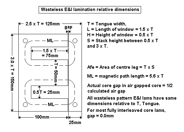
Fig 1. Wasteless E&I dimensions.

T sizes commonly available for E&I laminations with relative
dimensions shown above.
This pattern shape for E&I lams are known as the "wasteless"
or "scrapless" pattern, which
means that there are no wasted off-cuts when the sheet metal is
cut. E&I wasteless lamination
sizes are simply known by the Tongue size which for OPTs,
chokes, and PT for amplifiers may
have sizes :-
20mm, 25mm, 28mm, 32mm, 38mm, 44mm, 51mm, 62.5mm.
These correspond to former inch sizes = 0.75", 1.0", 1.125",
1.25", 1.5", 1.75", 2.0".
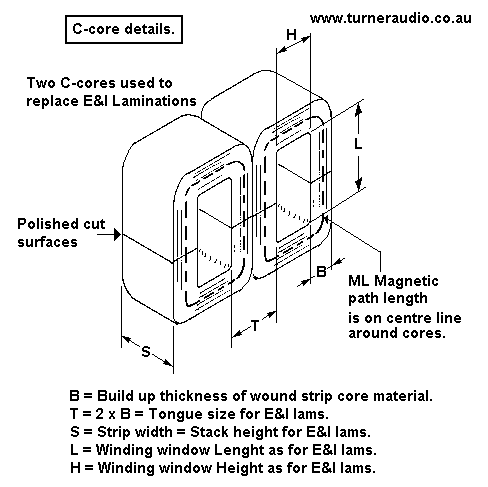
Fig 2. C-cores.

OPTs may use GOSS C-cores arranged above as "double 0" and these
will work very well for all OPTs.
But there are very many sizes available, and whatever is chosen
MUST have sufficient Afe and a window
big enough to contain wire turns and insulation.
Most C-cores favour design for low iron weight and higher copper
weight, giving less weight for any E+I
cored transformer. But this is only because very nearly all E+I
transformers are wasteless pattern where
L x H / T ratio = 28.5. and if anyone wants a non standard E+I
core pattern with higher window L x H / T
ratio, they will not find it easily. The Williamson OPT of 1947
used E+I with T32mm which had window
L75mm x H25mm so ratio = 58.6, very similar to C cores which
might be now chosen for the same OPT.
But the rules for good OPT design insist that Afe = 300 x
sq.rt Po; Po = ( Afe / 300 ) squared.
A large range of C-cores is available from www.nicore.co.cn
I do not know if they can supply DIYers wanting very small
quantities.
From their table for standard 0.3mm thick GOSS strip, selections
could be :-
Two x CD16x32x80 cores give Afe = T32mm x S32mm = 1,024 sq.mm,
window H25mm x L80mm.
Va-a 400Vrms, Fsat 14Hz, Np = 4,000t x 0.315mm Cu dia wire, RwP
188r.
OK for 20W to 8k0, weight 1.92Kg.
Four x CD16x32x80 cores ( stacked ) give Afe = T32mm x S64mm =
2,048 sq.mm, window H25mm x L80mm.
Va-a 566Vrms, Fsat 14Hz, Np = 2,828t x 0.375mm Cu dia wire, RwP
= 124r.
OK for 40W to 8k0, weight 3.84g.
Va-a 632Vrms, Fsat, Np = 3,157t x 0.355mm Cu dia wire, RWP =
154r.
OK for 50W to 8k0, weight 3.84Kg
Notice that the L x H / T ratio = 62.5, which always means more
copper turns than with lower ratio.
--------------------------------------------------------------------------------------------------------------------
E+I CORES EASIER FOR LOW NUMBER PRODUCTION
There is no strict rule to have T = S for a square section for
Afe with wasteless E+I.
I used T50mm x S110mm for 300W
PP amps. But usually S is not more than 2 x T. It is
often better
to try using a smaller T size than for square core, so S is
higher. OPT-1A theoretical Afe = 2,598sq.mm,
so possible cores are T51mm x T51mm, T44mm x S59mm, 38mm x 68mm.
But only the square core suits a standard bobbin, and the latter
two need stack increased to suit
bobbin sizes. This means increasing Afe beyond the minimum
required, but that will allow lower Np and
less copper. The design of all transformers involves the balance
of the weight of iron vs weight of copper.
Wasteless pattern E+I cores allow designers to use high iron
weight with fewer copper turns, but C-cores
allow low iron weight with higher copper turns.
The choice of core shape to suit bobbins and with higher Afe
sizes for smaller T are :-
T51mm x S51mm, T44 x S62mm, T38mm x S74mm or S85mm.
7. For OPT-1A, choose T 44mm, S 62mm, L 66mm, H 22mm,
wasteless E+I laminations.
Afe = 44mm x 62mm = 2,728sq.mm.
8. Calculate theoretical primary turns th Np based on
operation for Nominal 8k0 RLa-a,
and Po = 50W. Va-a = sq.rt ( RLa-a x Po ) = 632Vrms.
Th Np = 22.6 x Vrms x 10,000 / ( Afe x Fsat x Bac max ) where
22.6 and 10,000 are constants,
Afe in sq.mm, F in Hz, Bac in Tesla.
= 22.6 x 632V x 10,000 / ( 2,728sq.mm x 14Hz x 1.6T ) = 2,337t
9. Calculate window area portion for primary wire
including enamel coating.
Wanted window area for pri = 0.28 x L x H = 0.28 x 22mm x
66mm = 406.6sq.mm.
10. Calculate theoretical Primary wire dia, th Pdia. Each
turn of wire occupies area
= overall dia squared. Th pri oa dia = sq.rt ( 0.28 x L x H
/ th Np )
= sq.rt ( 406.6sq.mm / 2,337t ) = 0.417mm.
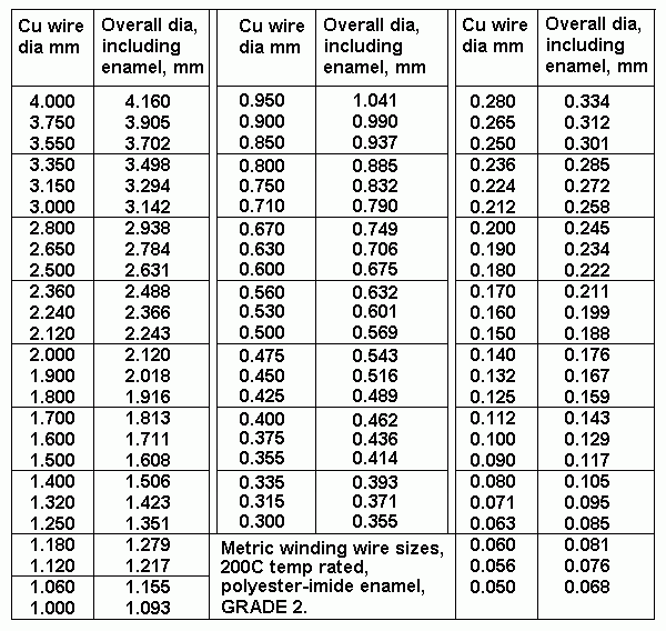
11. Find nearest suitable overall dia wire size from the
wire size table to th oa Pdia, mm.
Table 1. Available Wire Sizes.

Want oa dia not exceeding 0.417mm.
Try oa wire size = 0.414mm, Cu dia = 0.355mm.
12. Check safe Idc for chosen P wire = Cu area of
wire x 2Amp/sq.mm
= 22 x 0.355mm x 0.355 / 28 = 0.198Amps dc, say 200mAdc.
Idle Idc could be continuous 200mAdc in each 1/2 primary winding
without wire getting
too hot or fusing, which would require much higher Idc. 6550 or
KT88 would have Pda+g2
= 0.7 x Pda rating of 42W so Pda+g2 = 29W with Pda 26W and Pdg2
3W.
If Va-a = 632Vrms, then Va = 316Vrms = +/- 447Vpk, so idle Ea =
490Vdcand Iadc
= 26W / 490V = 53mAdc. KT120 could have idle Pda = 37W, so Iadc
= 76mAdc, all OK.
Estimated Rw for primary could be 5% x 8k0 = 400r, with 200r for
each 1/2 pri so wire heat
with 75mAdc = Rw x Idc squared = 1.13W = OK.
But if one KT120 has high Idc = 0.5Adc with bias failure, heat =
50W, and wire will get very
hot while enclosed between insulation layers and this may cause
damage to insulation on
turns and to layers of insulation so the amp MUST HAVE some sort
of active protection
circuitry to automatically turn off the amp if the Idc drawn by
one or more tubes rises to more
than twice idle Idc for longer than 4 seconds. I used such
measures in all amps I sold and
my customers were always happy that when their output tubes
eventually wore out and
began to conduct far too much Idc before dying, the amp turned
itself off and there was
no expensive repairs needed for OPT, PT, or to any other parts.
13. Calculate bobbin winding width, ie, traverse width
between cheeks of the bobbin, Bww.
NOTE. Most moulded bobbins for OPTs between 10W and 200W have
nominal cheek thickness
under 2mm. Therefore allow Bww = window L - 4mm. For OPT-1A, Bww
= 66 - 4mm = 62mm.
NOTE. Some OPTs are wound using a rectangular tube of phenolic
board 2mm thick without
cheek plates at each end of winding layers. Layers of insulation
are same width as window L.
The wire layers begin 2mm in from edge of insulation layer and
finish 2mm short of insulation
edge.
This manner of winding takes much more skill to keep layers neat
and tidy and has the
advantage that the crepage distance between layers of wire is
about 4.5mm, much more than
where all wire layers are brought to insides of bobbin cheeks
where they exist on a moulded
standard bobbin. However, the cheekless bobbin favours high Vdc
and high Vac over 1,000V,
where biggest peak Va + Ea difference could be 5,000Vpk.
Cheekless winding is not needed
for most OPTs where idle Ea = +500Vdc, and highest Vac = +/-
500Vpk.
The Sec windings are at 0V potential but the P-S insulation is
usually more than 0.4mm, and
with varnish available and the enamel used on Grade 2 wire, I
never ever found there was any
arcing on the many OPTs I wound.
14. Calculate theoretical P turns per layer.
Th P tpl = 0.97 x Bww / oa dia from Step 13 = 0.97 x 62mm
/ 0.414mm = 145 turns per layer.
The 0.97 factor is used because of difficulty filling the layer
with fine wire with oa dia < 0.5mm.
15. Calculate theoretical primary layers = th Np / th P tpl
= 2,337t / 145tpl = 16.117 layers.
There should be an even number of P layers for equal layers each
side of CT, and there should
NOT be any fractions of a layer, so for OPT-1A, use 16 P layers.
16. Calculate real Np = NpL x P tpl = 16 x 145t = 2,320t.
17. Check Fsat at Va-a for Nominal RLa-a, For OPT-1A,
Nominal or middle RLa-a = 8k0, and
clipping Po = 50W, where Va-a = 632Vrms.
Fsat = 22.6 x Va-a x 10,000 / ( Afe x Np x Bac max )
= 22.6 x 632V x 10,000 / ( 62 x 44 x 2,320 x 1.6 ) = 14.1Hz. So
far, my formulas are
working OK.
18. Why is Fsat at 14Hz? Many argue 28Hz is fine, which
means Np could be 1,160t. IMHO,
this may be OK for a cheap guitar amp, but not for Hi-Fi. The
highest forgivable Fsat for a 50W
amp should be 20Hz, reserved for those who just cannot accept
the slight extra cost of best
practice, so therefore stack height of 62mm could be reduced to
44mm.
Using OPT1-A with lower Ea = 400V with higher Iadc for more
class A Po will reduce maximum
Va-a from 632Vrms to about 525Vrms for 35W to 8k0, and this will
give Fsat 16.4Hz = OK.
19. Calculate average turn length, T L = ( pye x H )
+ 2 x ( S + T ) mm, where constant
pye = 3.143, or 22 / 7.
TL = ( 3.143 x 22 ) + 2 x ( 44 + 62 ) = 281mm.
20. Calculate primary winding resistance, Rwp = Np x
T L / ( 44,000 x Pdia squared ) ohms
where 44,000 is constant = 100,000mm / 2.26r for 100M x 1.0mm
dia wire ),
and Pdia is the Cu dia from the wire tables.
RwP = 2,320 x 281mm / ( 44,000 x 0.355 x 0.355 ) = 118r.
21. Calculate pri winding loss % with Nominal RLa-a =
8k0.
P loss % = 100% x RwP / ( Ra-a + RwP ) = 100% x 118r / ( 8,000r
+ 118r ) = 1.45%.
22. Is P loss % > 3.0%? If YES the design may require
larger core or window size to fit larger
dia wire. If NO, proceed to Step 23.
23. What is P loss % at minimum RLa-a? Min RLa-a = 4k0, P
loss % = 100% x 118 / 4,118
= 2.87% < 3% OK.
Forward to PP OPT Calc
page 3
Back to PP OPT Calc
Page 1
Back to Index Page


