PP OPT CALCULATIONS, PAGE 1.

There are 5 pages on design of Push Pull OPT design for beam tetrodes, pentodes, triodes.
Page 1 here has steps 1 to 4 for OPT-1A, followed by much general information.

Page 2 output-trans-PP-calc-2.html has steps 5 to 23.
Page 3 output-trans-PP-calc-3.html has steps 23 to 38.
Page 3A output-trans-PP-calc-3A.html has steps 39 t0 50.
Page 4 output-trans-PP-calc-4.html has steps 24TS to 41TS with Tapped Secondaries.
Page 5 output-trans-PP-calc-5.html has steps 1 to 34 for OPT-2A for AB triodes.

Load Matching.
For details about how to work out the primary loads for PP Beam Tetrodes, Pentodes, go to :-
loadmatch-4A-PP-tetrodes-pentodes.html
loadmatch-4B-PP-tetrodes-pentodes.html

1. OPT-1A.
Nominal load ratio is 8k0 : 4r0, 8r0, 16r0, with maximum 5% winding losses with each of the sec loads.
The design will be similar to what I found to be successful for 99% of my past customers using average
speaker sensitivity of 88db/W/M, and for use with 2 x 6550 / KT88 in PP class AB.
OPT1-A is suitable for the Integrated5050.html

Table 1. OPT1-A. Po for various loads.
Primary input
power from
2 x KT88, 6550
Class A
max Po
anodes
Class AB1
max Po
anodes
Pri
Load
RLa-a
Pri
Va-a
Vrms
Secondary
Loads
ohms, r
Total Rw
loss%
max
Sec
max Po

Power
quality,
use.
75W AB1
5.0W
75W
4k0
512
2r0, 4r0, 8r0,
8%
69W
Lo-Fi, guitar amps, PA
**50W AB1**
10.0W
50W
8k0
632
4r0, 8r0,16r0
4%
48W
Hi-Fi, fine music
23W A
23W
nil
16k0
655
8r0,16r0,32r0
2%
22W
Hi-Fi, ultra fine music.
OPT-1A is to have many possible sec loads between 2r0 and 32r0 to allow a very large range of speaker
types to be used and OPT-1A should give adequate power and fidelity.
The load matches are possible by means of using 3 different strapping patterns for secondary windings.
It is impossible to get only pure class A for 2r0 speakers but few speakers have a nominal Z of 2r0 for
main AF power band between 50hz and 500Hz.

It is not possible to get only pure class A Po to 4r0 unless an additional OPT secondary strapping
pattern included more subdivision of sec windings to get an additional load match for
8k0 : 2r0, 4r0, 8r0, 16r0.
It becomes difficult to design an OPT to give a range of Po between only class A Po and maximum class
AB Po to all speakers between 4r0 and 16r0.

WASTELESS SECONDARY WINDINGS.
The various strapping patterns give the same leakage inductance and same total overall winding resistance
without any portion of secondary turns not being included in carrying current, and with each secondary
wire having equal winding current density where possible. This aspect of OPT design was often
ridiculed and ignored by manufacturers who sold garbage to the unsuspecting public. Here is where
you learn to do it right.

2. Calculate OPT-1A power rating = Highest class AB Po from Secondary winding expected + 10%.
The 10% is chosen to cover the worst case winding losses where RLa-a is lowest and Po is highest. 
Power rating = 67.5W + 10% = 74.25W, say 75W.
Design the OPT-1A to give load ratio of Middle or Nominal Load ratios = 8k0 : 4r0, 8r0, 16r0,
Class AB Po = 48W for RLa-a 8k0, Fsat < 15Hz at Bac max 1.6 Tesla,
Bandwidth at 48W = 15Hz to 70kHz minimum, with low level bandwidth 3Hz to 70kHz.

3. Choose tubes to be used for OPT-1A, 2 x 6550 or KT88 or KT90 or KT120 with Idle Pda
< 0.7 x maximum Pda rating. See loadmatch-4A-PP-tetrodes-pentodes.html for PP beam
tetrodes and pentodes.

Choose mode of operation for PP tubes. Possible modes are :-
A. Beam Tetrodes or Pentodes, fixed Eg2, conventional operation without UL taps or CFB windings.
B. Beam Tetrodes or Pentodes, fixed Eg2, with CFB tertiary winding for between 12.5% and 20% CFB.
C. Beam Tetrodes or Pentodes with 50% UL screen taps.
D. Beam Tetrodes or Pentodes with 25% UL screen taps and with 12.5% to 20% CFB.
E. Triode connected tetrodes or pentodes.
F . Real Triodes such as 2A3, 300B.

PROCEED TO Page 2 output-trans-PP-calc-2.html
--------------------------------------------------------------------------------------------------------------------------------
Background Information.........
The Radiotron Designer's Handbook, 4th Edition, 1955, has good design advice about OPT design.
But "RDH4" is extremely difficult to read for anyone who has not gained a degree at a university for
electronics engineering, equal to what was available at universities in 1955. However, there are plenty
of craftsmen or tradesmen, hi-fi enthusiasts and DIYers who can learn a huge amount from RDH4 if
they are also willing to collect a few shelves of books also written about electronics before 1960.

Without the knowledge available in 1960 there is little available online and which explains vacuum tubes
and audio transformer design as well as the books written before 1960. All components in all amplifiers
can be broadly understood as mental concepts, but building amplifiers involves mathematics and
knowledge of electronic behaviours described in detail in RDH4 and many other books. Many electronic
phenomena seem to occur in a manner opposite to our common sense. Although my basic mathematics
and physics education level only extended to high school, I can comprehend the mathematical relationships
between Resistance, Capacitance and Inductance, and many formulas such as Ohm's Law.
I found RDH4 extremely useful and I gradually began to understand the full reason why the book was
written.

If you have no copy of RDH4, paper copies are occasionally for sale online. There are also scanned digital
copies but most use too few pixels so it becomes difficult to read because some letters printed on schematics
and text are 1/3 of full text size of printing.
RDH4 should have been written on A4 sized pages, 210mm wide x 300mm high, and not the 130mm x
210mm high. Reading an original book is far easier than trying to read a poorly scanned a copy on a CD.
The paper book allows easy faster use with its index list rather than using the index list then finding page
numbers on the CD copy. The paper book index does not automatically create html links to pages of text.
So the original RDH4 book is easier to navigate than anything in digital file form.

For OPTs, RDH4 Chapter 5 from page 199 to page 253 should be read repeatedly until the
message sinks in. It is not easy to understand if you have no idea about basic tube operation and other basic
electronic behaviours, so as soon as you find you don't understand something, you must find out about it from
somewhere else in RDH4 or from some other source. I ended up with a few shelves of books with overlapping
information. Most of these other books have never been published online and never will be, because it is now
the digital era, and vacuum tubes and analog electronics have become obsolete. Unfortunately, the associated
reference material listed for information on pages 252 to 253 has mainly been removed from library archives
to make way for the huge mountain of more modern knowledge. There is very little new information or better
information about output transformers written after 1960 because mainstream development for tube OPTs
stopped in about 1959 when all tube operated electronics was being dumped in favour of solid state and
miniaturized circuitry.

Not many folks will find RDH4 in any local library so I shall try to unfold the design method I have evolved
based on information in the RDH4 or other book sources. I gained most useful experience after 1994 when
I built a primitive winding lathe and began to wind OPTs, then test them, and then design better ones.

After having wound many very fine PP output transformers, some with bandwidth from 14Hz to 270kHz,
I feel well qualified to share my experience. The list of logic steps involved in producing the best possible
OPT is based on having low winding resistance losses, core saturation at full power at 14Hz, and adequate
interleaving to extend the HF response up to at least 50kHz without reliance on negative feedback.
This meant keeping both the leakage inductance and shunt capacitances to low quantities. The end result
gives a well filled winding window and efficient use of iron and copper.
Using my design pages for OPTs and choosing interleaving patterns in tables will always give very low
winding losses and wider bandwidth than many commercially made OPTs where the accountants have
been allowed to dumb down good design principles mentioned in RDH4.

Wasteless Secondaries on OPT.
My OPT designs usually give three possible secondary load matches for one value of primary load.
If the primary load RLa-a = 6k6, the secondary loads can usually really be say 3r6, 6r4, 14r4, so that
loads are not factors of 2.0 for each load change. This because fractions of sec windings do not change
by the awkward factor of 1.414 for each load change, and sec turns are often 3N, 4N and 6N for above
loads, which are suitable for nominal 4r0, 8r0 and 16r0. The result gives equal secondary Rw loss %,
equal leakage L, and same HF and LF response.

Notice 6r4 is less than 8r0 but its OK because a speaker may have nominal Z 8r0, but will have Z vary
between 5r6 and 40r for different bands of frequencies between 20Hz and 20kHz. For a 3 way full range
speaker with bass, midrange and treble drivers, the lowest Z may be where output from bass ends and
midrange begins, often where much audio energy exists, typically between 180Hz and 300Hz.
All amplifier devices for music work with load changing from one microsecond to the next.

The disadvantage of changing soldered links for the wanted speaker load is that non-skilled amp owners
must seek a competent electronics technician to change the amp "impedance setting".
They then sell the amp, and the next owner has no clue that OPT has been linked for 16r0 speakers,
and they then plug in 4r0 speakers and wonder why the amp smoked so easily when their teenage son
played some "rap music" with bass boosted at deafening levels. I have seen examples where Quad-II
amps set for 16r0 have been used for 4r0 speakers and sound was not good, even without provocation
by teenage son with "rap shit" from a digital source.

Tapped Secondaries on OPT.
Many amps made in 1960 had 4 terminals at amp rear panel labelled Com, 4r0, 8r0 and 16r0.
This usually meant the OPT has at least two identical parallel secondary windings each having turns
for 16r0. each 16r0 winding has tap at 0.71 x all turns for 8r0, and tap at 0.5 x all turns for 4r0.
This always means that best HF response and lowest winding losses are where Com-16r0 terminals
are used with load = 16r0. If using Com-8r0, 30% of sec turns are not used, and for Com-4r0, 50% of
sec turns are not used so that HF response and winding losses are worst when using 4r0 speakers
at Com-4r0.

The disadvantage of tapped secondaries is that owners get all confused when they have to connect
speakers to an amp, and somehow think the Com-16r0 terminals have more ohms so there's more
power available, and it seems to be true when 4r0 speakers are switched from 4r0 outlet to 16r0
outlet. Unfortunately, the amp with a row of 4 terminals Com, 4r0, 8r0, 16r0 can bamboozle many
owners.
There is a huge amount of stupidity about anything even slightly technical among most of the humans
of our little blue Planet. Two speaker cables can be connected to 4 output terminals in about 4 different
ways and there is a very high chance of many getting wrong.

A wife of owner or cleaning staff manages to disconnect speakers using a vacuum cleaner near amps
so they may plug speaker cable plugs back in, and then chance of getting it wrong is extremely high.

If there is a possible way an amp owner or his family and friends or domestic workers can damage
an amp or speakers, you can be 100% sure that a few of them will find out how to wreck the system
without being aware of just how they succeeded.
-----------------------------------------------------------------------------------------------------
At page output-trans-PP-calc-3A.html I show the recipe for OPT-1A. 4 x Sec layers are each 51t
but with one layer subdivided for 3 x 17t, The resulting load matches are :-
Table 2. OPT-1A loads and turns.
OPT-1A Pri RLa-a,
2,320t
Sec
4 // 51t
Sec
3 // 68t
Sec
2 // 102t
Po
Watts
4k0
1.9r
3.4r
7.3r
69W
8k0
3.9r
6.9r
15.5r
49W
16k0
7.7r
13.7r
30.9r
22W
Not one of the sec loads is exactly 2r0, 4r0, 8r0, 16r0, but they are close enough and where a speaker
= 8r0 exactly for one frequency, and with Sec = 3 // 68t, RLa-a becomes 9.27k and it makes little
difference to whole operation. The same speaker may be 6r0 at another frequency so RLa-a = 6.95k.

OPT-1A may have secondaries with sec layers = 57tpl for 4 // 57t, 3 // 76t, 2 // 114t which would give a
primary load of 6.94k to the same sec loads in Table 2, with slightly less AB1 Po and more initial
class A if wanted, depending on tubes which could be 2 x EL34, KT66, 6L6GC etc with lower idle
Ea but same Iadc.

Is there an OPT Calculator program? AFAIK, there is no available "Output Transformer Calculator"
program available anywhere so that you enter tube type, mode of operation, Output power maximum,
and after clicking "calculate", all the winding details appear on a sheet you can take to a person who
knows how to read the diagram and wind the OPT without asking you to not come back because
he / she thinks it just cannot be done.

I am not a computer coding expert, but there is a flow of logic and formulas for each step of the way
to an OPT worth paying for, plus background notes. Between 2003 and 2016, I helped five gentlemen
with university education to attempt to make a working program for audio OPTs. None succeeded and
none had the time or the mathematical skills to make a complex algorithm on which a design could be
done properly. I wanted no financial reward and I welcomed them to develop an "app" which they could
sell.

I found that to design a good OPT, tools needed were :- brain with IQ about 125+, PC with a printer,
Exercise book, pencil, pocket calculator, scale ruler, and open but serious mind, persistent attitude,
and lots of time, plus a relative known as Uncle Doubt, who tells you when you have made a mistake,
or that something just does not seem right.......

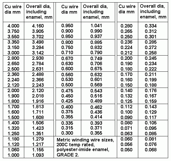
METRIC WINDING WIRE SIZE CHART
table-wire-sizes.GIF
The metric winding wire sizes were kindly given to me by a local Sydney wire and transformer parts supplier.
This chart is for "Grade 2", and the only grade stocked by my supplier because it is the industry norm for
99% of high temperature rated winding wire for electric motors and stressful industrial applications.
The range of sizes shown are not all obtainable off the shelf, and to get some sizes a wait for an order is
involved, so I sometimes have to design around the wire size available, adding to the challenge. Anyone not
used to measuring in millimetres should teach themselves because the metric system is so easy once you learn.
THE WIRE DIAMETER size must be known at all times and if you use wire gauges described as AWG,
SWG, BS, you will make huge mistakes and become confused and anxious, as you swear and curse while
using conversion charts for gauges, inches and feet. Before winding anything, make sure you have an accurate
micrometer to confirm that the size is correct.
Wire should be measured with enamel coating and with enamel carefully removed with a pen knife.
My micrometer is electronic and reads size at a small dial and in increments of 0.01mm, or 0.393 thousandths
of an inch. So it reads 0.30mm or 0.31 well enough without eye strain on a vernier scale. The battery goes
flat even if I turn it off, so I remove the battery when not in use for months between days where I work with
transformers.

Forward to PP OPT Calc page 2

To Index Page