PP OPT CALCULATIONS PAGE 4. 2016.

OPT-TS1 WITH TAPPED SECONDARY WINDINGS.

OPTs may have a Tapped Secondary Winding so an amp may have 4 output terminals most often
labelled Com, 4r0, 8r0, 16r0 to allow easy selection for most available speakers.

If an owner buys "4 ohm speakers", he plugs speaker cables between between Com and 4r0.
If he buys "8 ohm speakers" he plugs speaker cables between Com and 8r0.
( The letter "r" is used to mean "ohm", and reduces typing effort and shortens document length. )

Most of my OPT designs at this website have "wasteless secondary" windings where there may
be 3,4,5 or 6 Sec sections with one layers of wire but with one or more each layers subdivided
to allow soldered links to connect all the Sec windings in parallel or series patterns so suit a variety
of speaker loads and all secondary wires are used, and have equal current density.
OPT-1A has 4 sec layers, each 51t, with one divided into 3 windings of 17t. This allows the total 204
turns to be linked to give 4 // 51t for 4r0, 3 // ( 51t+17t ) for 7r1, and 2 // ( 51t+51t ) for 16r0.
The load matching is done using a soldering iron to change links on a terminal board rear of amp
or in the under-chassis area, and it can be completely confusing to many amp owners.

Unfortunately, amplifier owners are unable or unwilling to perform the simplest technical procedure
other than "plug it in and turn it on."
But owners then do not remember how the sec has been linked, and they buy new speakers with
different Z, or they sell the amp and the new owner does not know that load matching links are
adjustable so the amp may be linked for 16r0, but is used for 20 years with 4r0 speakers. And then
the owner does not realize there is a problem or poor load matching until a teenage son turns up
the volume to see how loud daddy's sound gear can go, and then a couple of tubes die, and maybe
other parts. But if the amp is linked for 4r0, and 16r0 speakers are used, the music sounds really
good, but it may not go loud enough. Amps get sold from one audiophile to another and nobody
remembers to check the notice which be on rear panel of all tube amps :-

MAKE SURE THE OUTPUT TRANSFORMER
HAS CORRECT LINK PATTERN TO SUIT YOUR SPEAKER.


I've never seen a surly notice like this on the rear panel of any tube amp. Owners lose their
paper book user manual, or there is no online information support.

Mis-match of amp to speakers may upset many audiophiles who will never ever understand any
technical issue even if repeated 69 times. Many could never be relied on to use a soldering iron
properly, or get the link pattern correct. Many lower power tube amps do not make as much
maximum as many solid state amps which are designed to work with all loads above 4r0.
Tube amps give their best music with good load matching of tubes to speakers via their OPT
with a choice of ideal loading terminals.

An OPT with "Tapped Secondary" and 4 output terminals avoids the ignorance and confusion with
linked secondary windings, but there is still a high chance of owners pugging speaker leads to
the wrong terminals, and they have no real idea what an Ohm really is, or a Volt, or an Amp.
-------------------------------------------------------------------------------------------------------------------------------
DESIGN HERE IS FOR OPT-TS1 and OPT-TS2.

BOTH suit a pair of 6550, KT88, KT90, KT120 used in the same way as for OPT-1A.
Both require the same design steps of 1 - 23 used for OPT-1A.

This page for Tapped Secondary has steps 24TS to 41TS.

For OPT-1A design, Step 23 on output-trans-PP-calc-2.html gives design results for E+I wasteless core,
T = 44mm, S = 62mm, L = 66mm, H = 22mm, TL = 281mm, ML = 245mm.
For RLa-a = 8k0, Primary Np = 2,320t in 16 layers of 145tpl, wire = 0.355mm Cu dia, RwP = 118r,
RwP loss % = 1.45%.
Step 23 selects P-S section interleaving pattern with 5P + 4S, and each secondary section has maximum
height allowance of 1.39mm.

From this point onward, the secondary design will be different to OPT-1A.

24TS. OPT-TS1 is to have 3 Nominal load matches close to 8k0 : 4r0, 8r0 and 16r0. With 4 Sec sections,
each wire layer must be a match to near 16r0. All Sec layers must be connected in parallel. One end of all
parallel layer sections is the Common terminal for 0V. The other end of all layers is 16r0.
Taps at centre of all layers is 4r0, and are all paralleled. Taps at 0.707 of layer turns is for 8r0, and all are
paralleled. All 4 connections to each of 4 sections are brought to amp terminals labelled
Com, 4r0, 8r0, 16r0.

25TS.For 8k0 : 16r0, ZR = 500 : 1, TR = 22.36 : 1, Secondary Ns = 2,320t / 22.36 = 103.7t, so round
down to even number 102 turns. 8r0 tap is at 0.7071 x 10²t = 72t and 4r0 tap is at 0.5 x 10²t = 51t.
Real Load ratios are :- 8k0 : 3r9, 7k7, 15r5.

Table 1. Np = 2,320t, and for 8k0 : 4r0, 8r0, 16r0.
Primary 2,320t
Nominal RLa-a
Sec 51t
ZR 2,069
Sec 72t
ZR 1,010
Sec 102t
ZR 517
Class AB
Anode Po
Class A
Anode Po
4k0
1r9
3r9 7r8
74W
5.0W
6k0
2r9
5r8 11r6
60W
7.5W
8k0
3r9
7r7****
15r5
48W
10.0W
12k0
5r8
11r6
23r2
35W
15.0W
16k0
7r7
15r4
30r9
26W
20.0W

26TS. From step 27, the maximum available sec winding height for each of 4 Sec sections
= 1.38mm.
Bobbin winding width = 62mm. 102 turns are wanted for 15r5 and wire size = 0.60mm oa dia.
Two x 0.6mm layers may be used with 0.05mm insulation between them to make sec section height
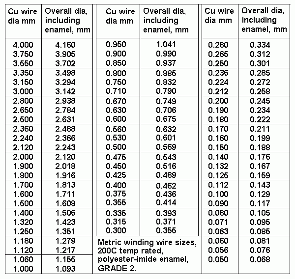
1.25mm = OK. Wire table shows Cu dia = 0.53mm for oa dia 0.6mm.

102t per layer is easily possible, and CT for 4r0 is at 51t, and 8r0 tap is at 72t.
Table 2. Wire sizes.
table-wire-sizes.gif
27TS. What is the full description of each tapped Secondary section )
Each has 2 layers each 102t x 0.53mm Cu dia wire, and each 102t winding has taps at 51t and 72t
so a loop of wire is brought out about 200mm from bobbin cheek and covered in woven polyester
sleeving pushed up to where the loop leaves the tap on a layer.
The two wires for the tap must be held firm by a turn of thin tape and some tape also used where
tap loop turns over onto other turns. The two loop wires must be kept side by side without crossing
over each other within the sleeving. 4r0 tap and 8r0 tap will exit cheeks on opposite sides to
make minimize bulge and keep following windings flat without dips or bumps.

28TS. Winding losses. Load ratio 8k0 : 3r9, 7r7, 15r5.
Calculate RwS for 3r9 windings with 8 x 51t which uses 1/2 of all secondary wire.
RwS = 51t x 281mm / ( 44,000 x 8 x 0.53mm x 0.53mm ) = 0.145r.
RwS loss % = 100% x 0.145r / 4.045r = 3.6%.

Calculate RwS for 7r7 winding with 8 x 72t, uses 0.707 x all secondary wire.
RwS = 0.205r. RwS loss % = 2.6%.

Calculate RwS for 15r5 winding with 8 x 10²t, uses all secondary wire.
RwS = 0.290r. RwS loss % = 1.84r.

RwP loss % = 1.44%.
Total P+S loss % for 3r9 = 1.44% + 3.6% = 5.04%.
Total P+S loss % for 7r7 = 4.04%.
Total P+S loss % for 15r5  = 3.28%.

Notice that Sec loss % is highest for 8k0 : 3r9 and Ns = 51t. For where 3r9 is used at Ns 72t,
RLa-a = 4k0, and total winding loss increases towards 10%. With 7r7 used at Ns = 51t,
RLa-a = 16k0, and total winding loss reduces towards 2.5%.

All these figures are quite good for the initial class A portion of Po, but increase by factor
of 1.4 while working in class AB above the A to AB threshold. Figures are better than I
found in mass produced amplifiers.

There is more work for winding tapped secondaries than for wasteless windings with links. 

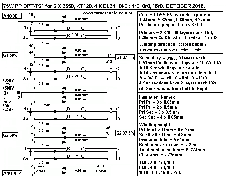
29TS. Draw winding diagram for OPT-TS1 :-
Fig 1. OPT-TS1 bobbin details.
OPT-TS1-75W-8k0-4-8-16.gif
Fig 1 shows OPT-TS1 secondaries = 8 layers 102tpl each with 2 taps and all paralleled.
The overall performance of OPT-TS1 is not much different to OPT-1A for output power.
Fsat will be same as OPT-1A.

30TS. High frequency behavior will be similar to OPT-1A for Ns = 102t. Secondary traverse winding
width for 73t and 51t is less than 102t which has full Bww = 62mm.

LL = 0.417 x Np squared x TL [ ( 2 x n x c ) + a ] / ( 1,000,000,000 x n squared x b )
where LL is Henry, 0.417 and 1,000,000,000 are constants,
Np is primary turns, TL is turn length mm, 2 is a constant because coil has magnetic flux loss at each
side of bobbin, n is number of P-S interfaces, b is winding traverse width.

NOTE. The unused turns with a tapped secondary have no current and act as though they are absent.
Leakage inductance LL is inversely proportional to winding width. If winding width is halved, LL doubles.
The magnetic coupling of primary to secondary of any transformer is never perfect and magnetic lines of
force "leak away" between windings. The amount of magnetic leakage is always equivalent to a
quantity of inductance that is in series with input to a winding. This leakage L makes negligible difference
to efficiency in PTs which operate at 50Hz only, but the reactance of LL increases with F so it may become
so high at 100kHz that almost no transfer of power can occur. For OPT design, the LL may be considered
as L in series with primary and it is minimized by interleaving sections of primary and secondary, and LL
is easily calculated in above formula.

I have never investigated if the formula for LL is completely linear. For the above geometric pattern with
5 x sec sections of 102t each, LL could be 3mH. But if each secondary was 10t of the same wire, winding
traverse width b is reduced by factor = 10 / 102 = 0.1, so winding width = 0.1 x 62mm = 6.2mm and
LL = 47mH. Load for 10t would be 0.16r for 8k0 at primary, and winding resistance loss would be high.
Maybe HF pole = 27kHz, much less than the calculated theoretical HF pole at 270kHz for 4.7mH calculated
below :-

For OPT-TS1 has LL = series inductance at primary
= 0.417 x 2.32 x 2.32 x 280 [ ( 2 x 8 x 0.7mm ) + 18mm / ( 1,000 x 8 x 8 x 62mm ) = 0.00295H
= 4.7mH.
XLL at primary = 8k0 at a theoretical 271kHz. The shunt C between anodes will prevent you
ever measuring the HF -3dB pole due to LL because XCa-a will be = 8k0 at a much lower F,
and it will be the dominant reactance at amp secondary output at HF, so there may be very little
reduction of HF response due to LL.
But for 4r0 tap, b is reduced by 1/2, and c is doubled and LL increases to 4.7H x 2 x 1.4 = 13.2mH.
XLL 13.2mH = 8k0 at 96kHz and LL increase may not make much difference to HF.
These F are above the AF band but must be considered where NFB is used to prevent HF
oscillations. reasons.

31TS. Shunt capacitance between ends of primary winding will be slightly more than for OPT-1A.
Capacitance between two metal plates C = ( A x K ) / ( 113.1 x d ) where capacitance is in pF,
A is the area in square millimetres of the plates assumed to be of equal area and shape, K is the
dielectric constant of the material between the plates, with air being = 1.0, 113.1 is a constant for
all equations to work, d is the distance in millimetres between the plates and is the same for the area
of the plates.

For OPT-TS1, there is some variation of turn length but calculations will be accurate enough if the
TL is the average for all turns with T 44mm and S 62mm = 281mm. Bobbin width = 62mm, so area
of each P-S interface = 281mm x 62mm = 17,422sq.mm. 0.38mm Nomex insulation has K = 3.2
approx but some of the gaps between turns is filled with varnish, so allow K = 3.4.

Allow for enamel coating 0.1mm, and wire curvature 0.14mm to make  d = 0.1mm + 0.14mm + 0.38mm
= 0.62mm.  C in pF = 17,422 x 3.4 / ( 113.1 x 0.62 ) = 845pF.
There are 4 x P-S each side of primary CT so total C = 3,380pF. Effective C from anode to 0V
= 3,380pF / 3 = 1,127pF. Therefore Ca-a = 563pF.

XCa-a 563pF = RLa-a 8k0 at 35.5kHz. This means the RLa-a reduces to 5k6 at 35.5kHz because
Ca-a is parallel to RLa-a. It will be found to be OK because C loading at 20kHz is low.

The resonance between Ca-a and LL = 5,035 / sq.rt ( LL mH x C uF ) = 5,035 / sq.rt ( 4.7 x 0.00056 )
= 98kHz, = OK. It is similar to OPT-1A.

32TS. How can slight HF loss at taps be minimized?
A. Each 102t winding may be wound in opposite direction across the winding width. The 51t for
Com - 4r0 for each winding is on each side of 1/2 the bobbin width so distance b = 62mm.
But distance c between P and S layers increases on one side of each secondary section because
1/2 the sec turns are not used, thus LL is unavoidably increased by about x 1.4 in this case.

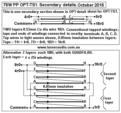
B. The 2 layers in each Sec section may each be 100t per layer. Each each may be 4 x 25t wound
QUADFILAR shown in Fig 2 below. This avoids taps anywhere along a winding so there is no bulge
over wire taps and all winding layers stay flat.
Each 25t in every layer extends across the 62mm. Taps are joins of winding ends outside the bobbin.
With RLa-a = 8k0, 50t = 3r7, 75t = 8r4, 100t = 14r8.
For Com-3r7, only 50t of each 100t layer is used, but they are spread across the whole 62mm width.
They have gaps between turns filed with un-used portion of layer and I do not know if the
LL increase where sec turns have gaps between turns. But it is good practice to use the whole width
of bobbin, and quadfilar is always the best way to have 4 equal windings in one layer to avoid taps
along the winding width.

The 4 quadfilar windings take slightly more time.
1 x 25t is wound across bobbin with roughly even gaps between turns.
The next 3 x 25t are wound across between gaps in first 25t.
Wires are pushed apart or together with a plastic paddle so that when 4 windings are on, they are flat,
with few gaps between wires. To make it easier to wind the second sec layer, use 0.15mm insulation
which assists how windings lay. There are 4 wire ends taken through both bobbin cheeks and slots
must be wide enough.
Each sec section will have 16 wire ends, with 8 emerging on each bobbin side.

Each 100t layer has 8 wire ends A-B,C-D, E-F, G-H. After winding is complete, there are 32 sec wire
ends on each side of bobbin to terminated to 4 terminals A, C, E, G on one side and B, D, F, H on the
other side.
Links between B-C, D-E, F-G are then connected. Terminals A = Common, B-C = 1r0, D-E = 4r0,
F-G = 9r0, H = 16r0. It is almost impossible to draw the the terminations without ending up with a
vision of a rat's nest. But it all becomes clear when you complete the assembly of transformer.

Fig 2. OPT-TS1 Secondary section details.
OPT-TS1-75W-quadrifilar-secs.gif
Load matches available for quadfilar secondaries, Ns = 25t, 50t, 75t and 100t.
The termination for 25t need not be ever used.

Table 3. OPT-TS2. Pri 2,320t to Sec 25t, 50t, 75t, 100t.
Nominal RLa-a
Primary 2,320t
Sec 25t
ZR 8,612
Sec 50t
ZR 2,153
Sec 75t
ZR 957
Sec 100t
ZR 538
Class AB
Anode Po
Class A
Anode Po
4k0
0r46
1r8 4r2
7r4
72W
5.4W
6k0
0r70
2r8
6r3
11r1
57W
8.0W
8k0
0r93
3r7
8r4**** 14r9
47W
10.8W
12k0
1r4
5r6
12r5
22r2
33W
16.1W
16k0
1r8
7r4
16r7
29r8
24W
21.5W

33TS. The OPT windings and all layers of insulation may be varnished while winding using slow
setting epoxy varnish brushed on or sprayed on varnish before each layer, then after each layer
with enough to wet all insulation.

Wire layers will bulge where they will be enclosed by core window so should be clamped with
G-cramp and neatly sized blocks of plywood. This may expel excess varnish, just what you want.
The wound bobbin should be left clamped up for a few days while epoxy sets hard. Plain spray varnish
may not harden much but clamping does tend to minimize bulge so E+I lams can be inserted easily.

With wound bobbin removed from lathe and free of clamps, E+I are inserted and insulated bolts and
yokes assembled, but kept loose. While loose, the whole transformer is soaked in vat of varnish for
an hour. Varnish may be slightly diluted to make it less viscous and more likely to penetrate all gaps
in core. after an hour, OPT is left for an hour while excess varnish can drain back into vat.

I often used yokes made of aluminium angles with holes drilled at each end, and for chassis mounting.
When bolts have nuts turned up tight, but no too tight, small sheets of plastic are used to wedge core
tight off the windings so that in 50 years, nothing can ever vibrate loose.

After all this fiddly work, terminals can be fixed near both cheeks of bobbin to connect sec wires which
can be reduced in length to less than 30mm to a terminal. It all becomes clear after you spend nearly
a day just to connect 64 wire ends to 8 terminals, and it all looks like a work of craftsman, and nothing
like the work of an idiot.
----------------------------------------------------------------------------------------------
34TS. OPT-TS2.
This OPT has Tapped Secondary for Nominal RLa-a 8k0 : 4r0 and 9r0.
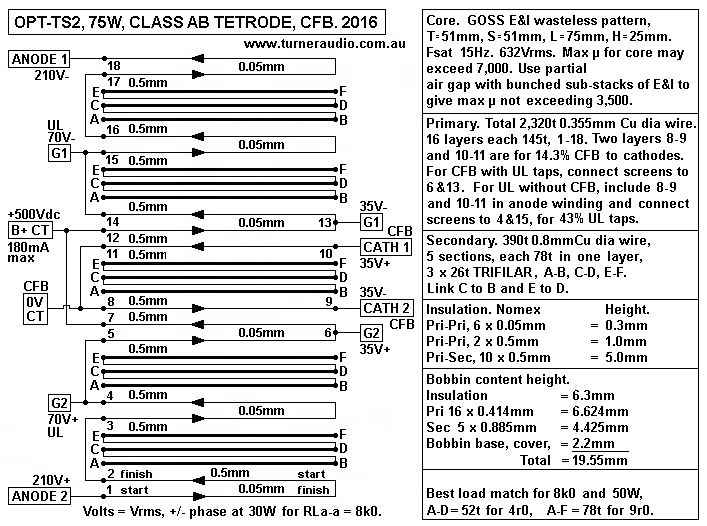
Fig 3. OPT-TS2 bobbin and all details.
OPT-TS2-75W-8k0-4r0-bobbin-CFB.GIF
Fig 3 OPT-TS2 uses GOSS T 50mm x S 50mm wasteless E+I with L 75mm x H 25mm.
Afe = 2,500sq.mm, TL = 280mm, ML = 280mm.
It is for 50W for 8k0 : 4r0 and 9r0, but max Po can be 74W.
This suits most people wanting to use 2 x 6550, KT88, KT90, KT120 with Ea 500Vdc,
Iadc 50mA for 6550 to 65mAdc for KT120. The Primary has 2,352 total turns 0.355mm
Cu dia wire, 0.414mm oa dia giving 14 layers of 168tpl. There are 6 primary sections
and 5 secondary sections for interleaving pattern 6P x 5S.
2 Pri layers of the total 14 may be used for 14.3% CFB. But there are other joins between
primary sections which may be used for UL screen taps. 
Triode operation will be very good.

Each Sec section has 1 layer of 78t of 0.8mm Cu dia wire, 0.885mm oa dia.
Each 78t layer is 3 windings of 26t and are wound TRIFILAR and are connected in series
outside the bobbin after winding is completed. The possible output load matches :-
Table 4. OPT-TS2 Pri 2,320t Sec 26t, 52t, 78t.
Nominal RLa-a
Primary 2,352t
Sec 26t
ZR 8,183
Sec 52t
ZR 2,045
Sec 78t
ZR 909
Class AB
Anode Po
Class A
Anode Po
4k0
0r49
2r0 4r4
74W
5.0W
6k0
0r73
2r9
6r6
60W
7.5W
8k0
0r98
3r9
8r8 ****
48W
10.0W
12k0
1r5
5r9
13r2
35W
15.0W
16k0
2r0
7r8
17r6
26W
20.0W
There are not many 16r0 speakers made so there really is no need to have a load
match for high power. If someone does have a pair of Tannoy dual concentrics made
in 1970, they will work just fine when plugged to Com-9r0 because they have
very high sensitivity.

35TS. Calculate total P+S winding losses, 8k0 : 8r8, 2,352t : 5 parallel 78t.

Primary Rwp = 2,352t x 280mm / ( 44,000 x 0.355mm x 0.355mm ) = 119r.
P loss % = 100% x 119 / 8,119 = 1.47%.

Secondary RwS for 5 // 52t = 52 x 280mm / ( 44,000 x 5 x 0.80mm x 0.80mm ) = 0.10r.
S Loss with 3r9 = 2.5%.
RwS for 5 // 78t = 0.15r, so loss with 8r8 = 1.73%.

Total RwP+S loss % for 3r9 = 4.0%, for 8r8 = 3.2%. Both < 5% OK

Secondary Ns = 26t. Sec RL = 0r98. Rws = 0.05r, S loss % = 4.76%.
Total P+S loss = 6.2% for 8k0 : 1r0. For 4k0 : 0.5r, total loss = 12.4%.
But 0.5r and 1r0 loads are never going to be used.

36TS. Primary inductance will be similar to OPT-1A and quite sufficient where core ยต > 3,500.
Fsat at 632Vrms for 8k0 = 22.6 x 632 x 10,000 / ( 50 x 50 x 2,352 x 1.6 ) = 15.2Hz = OK.

37TS. Leakage inductance, OPT-TS2,
LL = 0.417 x 2,352 x 2,352 x 278 x [ ( 2 x 10 x 0.6 ) + 18 ] / 1,000,000,000 x 10 x 10 x 71 )
= 0.00264H = 2.64mH.
Is XLL < RLa-a at 100kHz? XLL = 1.65k, so LL is low enough.

38TS. Shunt capacitance.
Capacitance between two metal plates C = ( A x K ) / ( 113.1 x d )
For OPT-TS2, A = average TL x Bww = 278mm x 72mm = 20,016sq.mm. I show 0.5mm insulation,
but it could be Nomex 0.51mm and d with wire enamel and wire curvature = 0.75mm. Dielectric
constant, K, = 3.7. C at each P-S interface = 20,016sq.mm x 3.7 / ( 113.1 x 0.75mm )
= 873pF.
0.25mm Nomex has K = 2.7. One might assume two layers make 0.50mm and K remains 2.7,
but I don't know if it is true so I will stay with 0.51mm Nomex with K = 3.7.

There are 5 x P-S interfaces for each 1/2 primary, so total C = 5 x 873pF = 4,365pF and Ca-0V
at each anode to 0V = 4,365pF / 3 = 1,455pF so Ca-a across primary = 727pF.

XCa-a 727pF = 8k0 at 27.3kHz, and RLa-a = 5k6 with the Ca-a parallel to RLa-a.
If 2 x KT88 with UL taps have Ra-a 5k6, Ra-a // RLa-a = 3k3 and measured F response is -3dB
at 159,000 / ( 3,300r x 0.000727uF ) = 66kHz.
If load ratio is 8k0 : 4r0, ZR = 2,000:1, so 727pF across primary is equal to 727pF x 2,000 at sec
= 1.45uF.
So what happens when there is additional C loading?
In many older tube amps with GNFB, the use of a 0.22uF cap across output without any parallel or
series R load causes additional phase shift and severe HF oscillation at F above 70kHz. Use of a
2uF cap would not cause HF oscillation, but would cause a peak in F up to +6dB between 15kHz
and 35kHz, often with a rise of +3dB at 20kHz. These problems driving C are usually due to high
LL because of inadequate interleaving, say 50mH instead of 5mH.

ESL speakers often low Z between 10kHz and 20kHz due to their capacitance.
Quad ESL57 and ESL63 impedance curves are shown at quad2powerampmods.html
ESL57 have flat Z from 1kHz to 2kHz = 11r0, resistive, and response dips -3dB at 5kHz, so shunt
C = 159,000 ( 11r0 x 5kHz ) = 2.89uF, which has Xc = 3r0 at 18kHz, and just exactly why ESL57
has lowest Z = 1r8 at 18kHz is unknown, but maybe likely to be result of leakage LL in their step
up transformer becoming series resonant with the C at 18kHz with Z at Fo > 1r0.
To get Fo = 18kHz with C 2.89uF, the series LL = 0.027mH.

The 2 x KT66 in Quad-II amps coped OK with the very low load because the music energy between
say 5kHz and 20kHz has average of less than 1/10 of average of all other frequencies. Any amp is
considered to be able to drive any ESL57 OK if the
following network is used :- 15r0 in parallel with ( 2uF in series with 1r5 ). But this simple network
does not behave to produce the difficult HF Z curve for the ESL57, and it should have say 2u7 in
series with 0.03mH in series with 1r5. The 15r0 has very little effect at above 5kHz.

At the secondary of OPT-TS2, the LL of 2.64mA at primary becomes 0.00132mH at Sec. This LL
will add to input L of ESL57 step up trans and may produce a slightly higher Fo.
2 x KT66 can give 25.3Vrms to 32r0 for 20W at say 80Hz. But at 1kHz, load is 11r0, and KT66 could
manage about 25W and 16Vrms, and at 18kHz load is 1r8 and max Vo = 3Vrms for about 5W.
Therefore you could only ever plot the F response of amp or acoustic response of speaker with
Vo set at 3.0Vrms, to avoid any overload effects at HF, using Quad-II amps.
An amp with KT88 and OPT-TS2 would have such a tightly controlled Rout < 0.3r that the interaction
with LCR properties of an ESL speaker does not produce a peaked response below 20kHz, or a
peaked response more than +3dB above 20kHz nor is their any HF oscillation.

Speaker loads above 20kHz can be inductive with Z above 20kHz, so by 100kHz, a 4r0 speaker may
have Z = 20r, so output tube gain becomes high with a risk of HF oscillation with GNFB. The OPT
XLL increases at HF making tube load higher gain higher and to avoid the possible HF instability
is is good practice to connect Zobel networks across each 1/2 primary on OPT, say 3k9 + 0.001uF
and by 80kHz the RLa-a becomes about 8k0 if there is no load at sec.

39TS. LL and shunt C resonance. LL in series with each end of primary = 1/2 the value calculated for
whole primary = 1.3mH.
Fo = 5,035 / ( square root [ 0.00084uF x 1.3mH ] ) = 152kHz, above the AF band, = OK.

40TS. OPT-TS2 has bobbin content height = 19.55mm. Core window H = 25mm, allowed bobbin
content should not exceed 0.8 x H = 20mm, and if bobbin base = 2mm, there is 3mm clearance
between core and bobbin content. With 0.38mm insulation instead of 0.5mm, there is 4.2mm.

Forward to
PP OPT Calc page 5

Back to
PP OPT Calc Page 3

PP OPT Calc Page 3A

PP OPT Calc Page 2

PP OPT Calc Page 1

Index page