PP OUTPUT TRANSFORMER CALCULATIONS, Page 5.

For OPT-2A for PP class A1 and AB1 TRIODE CLASS A1 and AB1.
This page has steps 1 to 32.

1. The example title for Triode OPT will be OPT-2A, used for 2 x 6550, KT88, KT90, KT120 with
Ea = +500V, Ia dc = 50mA in each tube at idle. Load conditions are same as OPT-1A. TRIODE loadline
analysis for 2 x 6550 is fully explained at loadmatch3-pp-triodes.html

OPT-2A should work well with 300B with lower Ea = 450V, Iadc = 55mAdc.

What are the load matches wanted for 2 x PP 6550 triodes?
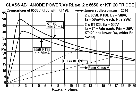
Graph 1. Po vs RLa-a trioded tetrodes.
KT120-KT88-Triode-PO-Vs-RLa-a-Ea500V-feb2012.gif
Graph 1 gives maximum anode Po for THD < 2% near clipping versus RLa-a for sine wave input for
2 x 6550 or KT88, or 2 x KT120. For maximum class AB1 Po, The minimum RLa-a can as low as 2k0
and is lower than for tetrode with same idle Ea and Iadc. This is because the Ra curve for Ea = 0V
shows that to get near same Va pk minimum as for tetrode the grid Vg1 would have to become very positive
which requires high peak grid input current on positive Vg1, in other words, the tubes will need cathode
follower drive to grids for class AB2 operation. Nevertheless, the Ra curve for 0V has average resistance
value of about 1,100r, and it is a "diode line" as mentioned for tetrodes and the Ra curve defines the limit
for class AB1 negative going Va pk swings.

For 2 x 6550, the ideal Nominal class AB RLa-a will give initial class A Po = roughly 25% of the max
class AB Po. With 2 x 6550, highest possible class AB1 Po = 40W, so we should expect initial class A Po
= 10W. Class A Po = 0.5 x Iadc squared x RLa-a, where RLa-a is lower than the load for only pure class A.
We know Iadc = 50mA for 6550, and class A Po so RLa-a =  2 x Class A Po / Iadc squared
= 2 x 10W / ( 0.05A x 0.05A ) = 8k0.
From Graph 1, with RLa-a = 8k0, we see max class A Po at 10W, and max class AB Po = 30W, so that
class A for the Nominal RLa-a is about 1/3 of the AB Po for this load.

For KT120, Max possible class AB = 50W, so for the Nominal class AB RLa-a we may expect
class A Po = 25% of 50W = 12.5W. The idle Ia = 70mAdc.
Nominal RLa-a = 2 x 12.5 / ( 0.07 x 0.07 ) = 5k1.
With RLa-a = 5k1, Graph 1 shows class A Po = 12.5W and class AB1 max = 41W, which is just over
3 times the the initial class A Po.

Extremists would lynch me from a gum tree because I am advocating class AB, something which upsets
them because of their reverence for triodes, where Po should if possible always be pure class A,

However, countless listening sessions with all tubes mentioned so far and including 300B and 2A3 led me
to conclude class AB was entirely forgivable, and the OPT is usually much easier to wind. At no time would
I ever stoop to the compromised philosophy where someone simplifies OPT design at the expense of good
music!

The OPT for a maximum of 20W of only pure class A for 2 x 6550 requires primary RLa-a = 16k5, or
twice the Nominal RLa-a. For 2 x KT120, the max class A Po of 27W is produced with RLa-a = 11k7,
and also roughly 2 x Nominal RLa-a.

To keep the Triode Extremists happy, the OPT should have Nominal RLa-a but with sufficient secondary
load matches to give pure class A Po with any load above say 2r0. An OPT with load ratio of 8k0 : 4r0, 8r0
or 16r0 cannot deliver pure class A Po to 4r0. The simple answer is to add a load match for 2r0, and with
4r0 speaker connected to 2r0 outlet, the RLa-a becomes 16k0, and near enough for only pure class A.

Basic properties OPT-2A :- Nominal Load Ratios 8k0 : 2r0, 4r0, 8r0, 16r0.
Nominal Po rating = Max Power Po for Class AB1 + 20% = 50W + 20% = 60W
for minimum RLa-a. Highest P+S Rw loss % for class A operation < 7%.

2. From load matching page for PP 6550 triodes, loadmatch3-pp-triodes.html we have :-
Nominal load ratio :- 8k0 : 2r0, 4r0, 8r0, 16r0. Output power = 41W for 2k5. Allow for KT120
and Po = 60W for 2k0.
The largest expected Va swing is for pure class A Po where Po = 21W, RLa-a = 16k0, Va-a = 580Vrms.

Calculate core size, Theoretical Afe = 300 x sq.rt ( audio power, Watts ) = 300 x sq.rt 60 = 2,323.8 sq.mm.
3. Calculate T and S sizes for core. For a square section Afe, theoretical tongue dimension T = S
= square root th Afe = sq.rt 2,323.8 = 48.2mm.
Choose suitable standard T size from list of available wasteless E&I laminations with T sizes :-
20mm, 25mm, 28mm, 32mm, 38mm, 44mm, 51mm, 62.5mm.
The T x S sizes can be T 51mm x S 46mm, or T 44mm x 53mm. Both will have same necessary Afe,
and we may choose what will be suitable with available moulded plastic bobbins with dimensions = say
T51mm x S51mm or T44mm x S51mm. The T51mm will make a much heavier OPT than the T44mm,
but T51mm will have a larger window giving lowest Rw losses. IMHO, there may be little need to use
51Tmm material.
Let us choose GOSS lams with T = 44mm, plastic bobbin with T44mm, and S51mm.
NOTE. Some constructors will be using non wasteless pattern E&I lams or or C cores which do not have
the same relative dimensions as E+I Wasteless Pattern cores. The actual sizes of the T, S, H, and L for any
proposed core MUST provide the wanted Afe and big enough window size.

4. Confirm all sizes for wasteless pattern E&I core. Adjusted Afe = 2,244sq.mm, T = 44mm, S = 51mm,
Window L = 66mm, H = 22mm.

5. Calculate theoretical primary turns =
th Np = [ square root ( class A RLa-a x class A Power ) ] x 10,000 / Afe
= [ sq.rt ( 16,000r x 21W ) ] x 10,000 / 2,244sq.mm = 2,584 turns.

6. Calculate Fsat for Pure class A RLa-a 16k0 at max class A Po 21W =
Fsat = 22.6 x Va-a x 10,000 / ( Afe x Np x Bac max )
= 22.6 x 580Vrms x 10,000 / ( 2,580t x 2,244sq.mm x 1.6Tesla ) = 14.1Hz. OK.

7. Calculate theoretical Primary wire dia, th Pdia.
NOTE. The Primary wire used for the transformer will occupy a portion of the window area
= 0.28 x L x H approx.
The constant of 0.28 works for most OPT. Each turn of wire occupies area = overall dia squared.
Overall or oa dia is the dia including enamel insulation.
Theoretical oa dia wire = square root ( 0.28 x L x H / th Np ) = sq.rt ( 0.28 x 66mm x 22mm / 2,584t )
= sq.rt 0.1573 = 0.397mm

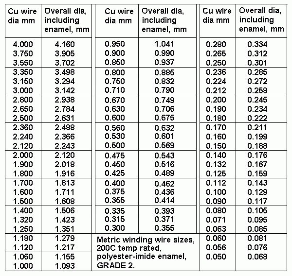
8. Find nearest suitable overall dia wire size to 0.373mm from wire size table, oa Pdia, mm.
Table 1. Available Wire Sizes.
table-wire-sizes.GIF
Choices are :- 0.393mm oa dia for Cu dia = 0.335mm. It is possible 0.414mm oa dia x 0.355mm Cu dia
will also be OK. NOTE. Using slightly larger wire will slightly reduce Np and increase Fsat. 
Try wire size 0.355mm Cu dia with oa dia = 0.414mm. Np possible = 0.28 x L x H / ( oa dia squared )
= 0.28 x 66 x 22 / ( 0.414 x 0.414 ) = 2,372t. Above we calculated theoretical Np = 2,584t for
Fsat = 14.1Hz.
Fsat is inversely proportional to Np, so if th Np = 2,372t, Fsat = 15.0Hz = OK.
9. Calculate nominal bobbin winding width between bobbin cheeks Bww = 66mm - 4mm = 62mm.

10. Calculate theoretical P turns per layer = 0.97 x Bww / oa dia wire. The 0.97 factor allows for imperfect
layer filling. th P tpl = 0.97 x 62mm / 0.414mm = 145.2 turns. Use P tpl = 145t.

11. Calculate number of primary layers.
Theoretical no of layers NPL = ( th Np from step 8 ) / P tpl from step 10, = 2,372t / 145t = 16.36 layers.
NOTE. All PP OPT should have even number of turns each side of the CT to avoid a CT in the middle
of a layer.
The calculation of theoretical primary layers will always be an odd or even number with a fraction of
a layer. For an odd number, round up to next above even number, for an even number, omit the fractions
of a layer.
For OPT-2A, Number of P layers = 16.0

12. Calculate actual Np turns = No P layers x P tpl = 16 x 145t = 2,320t.

13. Calculate average turn length, TL = ( pye x H ) + 2 x ( L + H ) = 3.143 x 22mm + 2 x ( 44 + 51 )
= 259mm.

14. Calculate primary winding resistance, Rwp = Np x TL / ( 44,000 x P Cu dia squared ) ohms,
where 44,000 is constant = ( 100,000mm / 2.26r for 100M x 1.0mm dia wire ) and P dia is copper dia
from the wire tables. OPT-2A, Rwp = 2,320 x 259 / ( 44,000 x 0.355 x 0.355 ) = 108r.

15. Calculate pri winding loss % with Nominal RLa-a = 8k0.
Pri loss % = 100% x Rwp / ( RLa-a + Rwp ) = 100% x 108r / ( 8,000r + 108r ) = 1.33%.

16. Is Rwp more than 3%? If YES, the design calculations must be checked and perhaps a larger core
stack or window size chosen. If NO, proceed to step 17.

17. Check wire size has Idc density < 2Adc per sq mm, and idle heat in primary winding.
Maximum Idc for primary wire = area of copper wire section x 2A = ( pye x Cu dia squared / 4 ) x 2A
= ( 3.143 x 0.355 x 0.355 / 4 ) x 2 = 0.198Adc. Is this at least twice the expected maximum idle Idc?
Expected maximum Idc for KT120 will be 70mAdc, and could be be 99mAdc. Max heat in P winding
= Rwp x max Idc squared = 108r x 0.099 x 0.099 = 1.06W = OK. The OPT will hardly ever feel
warm to touch.

NOTE. If ONE 6550 has bias failure and conducts 0.5Adc, Pdw in 1/2 primary winding = 51r x 0.5 x 0.5
= 12.75W and winding will get hot enough to perhaps melt the insulation. 0.355mm dia wire is trapped inside
other layers of wire which prevent heat easily radiating away from transformer. If Idc reached 2A for 1/2
the primary, Pd Rw = 51r x 2 x 2 = 204W, and wire can fuse open easily. Therefore, with 2 x 6550, KT120 etc,
it is important to have a sensitive enough fuse in series with HT winding in case a tube forms a short circuit
between B+ and 0V so that If Idc input to the CT of OPT reaches 0.5A, the fuse blows. If the OPT is used
with a short circuited speaker cable or speaker load at sec, and gain is turned up high with signal present,
the maximum average Idc could exceed 400mA. It is also necessary to build the amp with active protection
to automatically turn itself off where one or more output tubes conducts more than 2 x idle current for longer
than 4 seconds. This measure is more reliable than a fuse.

18. Choose the interleaving pattern for 30W OPT from tables 2, 3, 4, or 5 shown fully at
loadmatch3-pp-triodes.html

Table 4

Total P
layers
Primary and Secondary
layer distribution.
P&S
section pattern
35W to 120W 14 p S - 3p - S - 4p - S - 4p - S - 3p - S 5S + 4P

14p
2p - S - 3p - S - 4p - S - 3p - S - 2p 4S + 5P

16p
S - 4p - S - 4p - S - 4p - S - 4p - S 5S + 4P

16 p 2p - S - 4p - S - 4p - S - 4p - S - 2p 4S + 5P

18p S - 4p - S - 5p - S - 5p - S - 4p - S
5S + 4P

18p
2p - S - 5p - S - 4p - S - 5p - S - 2p 4S + 5P

20 p S - 5p - S - 5p - S - 5p - S - 5p - S 5S + 4P

20p
2p - S - 5p - S - 6p - S - 5p - S - 2p 
4S + 5P

22 p S - 5p - S - 6p - S - 6p - S - 5p - S
5S + 4P

22p
2p - S - 6p - S - 6p - S - 6p - S - 2p 4S + 5P
Choose interleave pattern for 16 primary layers, for up to 50W. Pattern can be 4S + 5P or 5S + 4P.
For OPT-2A, Choose 4S + 5P interleaving pattern = 2p - S - 4p - S - 4p - S - 4p - S - 2p.

19. Choose insulation thicknesses. 0.05mm insulation is used between primary layers to lessen possibility
of shorted turns even where the layers have similar Vac and Vdc, and to facilitate winding with small
diameter wire. For where there is large Vdc or Vac difference between adjacent primary layers or between
all primary layers and secondary layers the insulation must be thicker to prevent arcing and to lower the
shunt capacitance.
Minimum Insulation thicknesses should be selected from the insulation thickness table :-
Table 2. Vpk vs Insulation thickness
B+ CT
Vdc
Max Volts
peak
across
insulation. 
Minimum
thickness,
Polyester
sheet.
0V
100V
0.05mm
0V
400V
0.15mm
300V
600V
0.3mm
400V
800V
0.4mm
500V
1,000V
0.5mm
600V
1,200V
0.7mm
800V
1,600V
0.9mm
1,000V
2,000V
1.2mm
1,200V
2,400V
1.5mm
For OPT-2A, Calculate probable peak Vac + Vdc between P&S windings :-
500Vdc plus 500Vpeak Vac swing = 1,000V. Insulation thickness = 0.5mm.
Primary to primary insulation with less than 50V difference = 0.05mm. This 0.05mm insulation
between primary layers is not needed for insulation because Grade 2 winding wire has polyester-imide
enamel with much higher V rating. However, it is good practice to use the 0.05 insulation between all
Pri-Pri layers because winding consecutive layers becomes easier and there is less chance of getting uneven
surface of wound wires and less chance of getting gaps between turns and if the 0.05 is opaque, or of
white color, the turns can be seen much better by the winder.

NOTE. Insulation may be thicker than the minimum selected to achieve lower shunt C to extend HF response
and reduce phase shift for above 10kHz to make stabilisation with NFB easier and more reliable, especially
where RLa-a is between 10k0 and 30k0.  

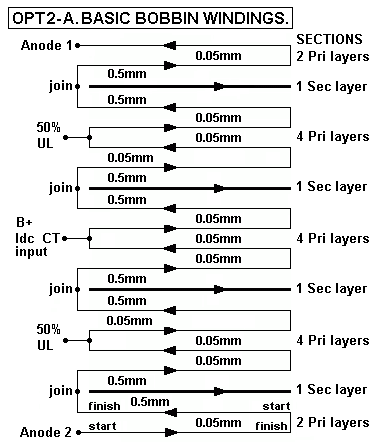
20. Draw basic interleaving pattern OPT-2A for PP triodes or UL, and without CFB.
Fig 1. Basic interleaving.
OPT-2A-basic-interleave-sketch-pp-triode.gif 
Fig 1 shows basic interleaving pattern for bobbin winding layers chosen so far, and shows the build up of
concentric layers from the bottom to the top of a bobbin, with traversing direction alternating for every wire
layer.
Insulation for OPT-2A :-
Pri-Pri wire layers with V difference is less than 10V, use 11 insulation layers x 0.05mm = 0.55mm height.
Pri-Sec, between all pri and sec, 8 insulation layers 0.5mm = 4.0mm height. Total thickness of all insulation
= 4.55mm.

21. Calculate height of Primary layers and all insulation = 16 Layers x 0.414mm oa dia = 6.624mm.
Height of all insulation layers = 4.55mm.
Total height of Primary + all Insulation = 6.624 + 4.55mm = 11.174mm.

22. Calculate max theoretical oa dia of Secondary Wire.
Calculate Available height in Bobbin = 0.8 x H window dimension = 0.8 x 22mm = 17.6mm.
Available Sec height = ( Available height in bobbin ) - ( Height P + all Insulation ).
Height of secondary wire layers = Available bobbin height - ( height of all insulation + primary wire layers )
= 17.6mm - 11.174mm = 6.426mm.
Th Sec oa dia = ( height all sec layers ) / no of sec sections with one layer each = 6.426mm / 4 = 1.607mm.

23. Choose maximum wire size from Table 1 above with o/a dia less than maximum in step 22.
There are 2 wires sizes which could be considered, 1.608mm o/a dia for Cu dia = 1.50mm, which is only
0.001mm larger than the allowed wire size 1.607mm in step 22. Or there is 1.506mm o/a dia for Cu dia
= 1.40mm. Either wire size may possibly be used.

24. Calculate the theoretical Sec turns per layer with maximum wire oa dia, Sec tpl = bobbin winding
width / max oa dia.
For 1.50mm Cu dia, th tpl = 62mm / 1.608mm = 38.55t, omit fraction, tpl = 38tpl. 
For 1.40mm Cu dia, th tpl = 62mm / 1.506mm = 41.17t, omit fraction, tpl = 41tpl.

25. Calculate load match with Np and th S tpl. TR for 2,320t : 41t = 56.58 : 1, ZR = 3,201 : 1.
If  RLa-a = 8k0, Sec RL = 2.5r for 41t. For only pure class A with Ea 500V, Iadc 50mA per tube,
class A RLa-a = 16k0 approx. For the 2,320t : 41t, the load ratio will be 16k0 : 5r0. This indicates you cannot
expect to get only pure class A with loads below 5r0, but forma 4r0 speaker, RLa-a would be 12k8, and giving
initial class A Po = 16W, with 25W class AB, which is a very good result. However, the 41 turns could be
reduced to 37t to get 16k0 : 4r0 ratio for Triode Fanatics.

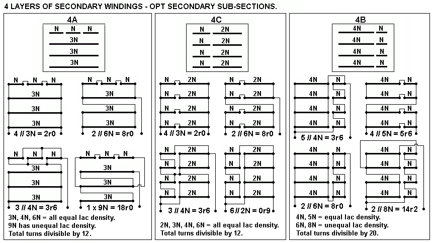
26. I have expanded information on OPT secs where there are 4 sec sections :-

Fig 2. 4A, 4B, 4C sub-sections.
opt-sec-4ABC-strapping-sub-sections.GIF
Examine possibilities using 4A.
Above, we calculated each sec layer with largest possible wire size of 1.5mm or 1.4mm Cu dia gives 38tpl or 41tpl.
For total sec turns = 4 x 38t = 152t. This total is not exactly divisible by 12, so the total Sec turns must decrease to
144t or increase to 156t to be exactly divisible by 12. This means tpl will be 36tpl or 39tpl.

Using 1.5mm Cu wire, turns per layer cannot exceed 38t, but could easily be 36t, with average gap between
turns = 0.114mm.

Using 1.4mm Cu wire, turns per layer cannot exceed 41t, but could easily be  39t, with average gap between
wires = 0.086mm.

The choice of 36t or 39t for Sec tpl gives 16k0 : 3r8 or 4r5. Both choices are acceptable, and turns are
suitable for pattern 4A and 4C.

27. Load matches available with 4 x 39tpl, 2 x 6550 triodes, class A to class AB.

Table 3. ZR for Np 2,320 : Ns = 39t, 52t, 78t, 90t, 117t. For 2 x 6550, KT88 TRIODE. Sec pattern = 4A.
2,320t
RLa-a :-
39t ZR
3,539
52t ZR
1,991
78t ZR
885
117t ZR
393
Anode
A Po
Anode
AB Po
Hi-Fi
quality
2k0
0r6
1r0
2r3
5r1***
2.5W
37W
Awful
3k0
0r8
1r5
3r3
7r6
3.4W
40W
Awful
4k0
1r1 2r7 4r5***
10r2
5.0W
38W
Awful
6k0 1r7
4r0
6r8
15r2
7.5W
34W
Tolerable
8k0
2r3
5r3***
9r0 20r4
10W
30W
Good
12k0
3r4
8r0
12r0
30r5
15W
25W
Very good
16k0
4r5*** 10r6
18r0
40r7
20W
21W
Best
24k0
6r8
16r0
27r1
61r1
18W
nil
Best
There are 4 useful load ratios which allow nearly all class A Po for sec loads low as 4r5 where Ns = 39t.
The same 4r5 load could be connected to Ns 78t which reduces RLa-a to 4k0, and class AB1 Po = 38W for
those addicted to high Po in class AB with low initial class A Po.
Even with a 2r3 speaker connected to Ns 39t gives 30W of good AB Po with load ratio 8k0 : 2r3.
The maximum Vo for 4r5 connected to 39t = 9.5Vrms. There is nothing to stop anyone connecting a 16r0
speaker to 39t where the RLa-a becomes 56k6, and class A Po = 6W max, which would make sense if the
speakers were horn loaded. The amp would have quite negligible THD. The same 16r0 could be connected to
Ns = 117t, and Po = about 32W class AB. There are probably quite enough options for anyone.

The use of KT120 will give very similar tabled figures as for 6550, KT88 where idle Iadc is the same.
If Iadc is higher, there is a slight increase of initial class A, and higher max Class A Po, but the the loudness
difference is negligible, but there may be some change to sound which will be instantly detectable by those with
Golden Ears, and with more $$$ in their wallets.

Use of Sec pattern 4C would give all the above load matches plus an additional match with Ns = 26t, giving
ZR = 7,962 : 1, which would allow pure class A Po with a speaker of 2r0. 

28. Pattern 4B requires total Sec turns be divisible by 20, and the secondary winding Tpl of 39t must be
increased to 40t. The same 1.4mm Cu dia wire with o/a dia = 1.506mm can be used, and will better fill the
winding width.

Table 4. ZR for Np 2,320 : Ns = 32t, 40t, 48t, 80t, 100t. For 2 x 6550, KT88 TRIODE. Sec pattern = 4B.
RL-a-a,
2,320t
32t ZR
5,256
40t ZR
3,364
48t ZR
2,336
64t ZR
1,314
80t ZR
841
120t ZR
373
Anode
A Po
Anode
AB Po
Hi-Fi
quality
2k0 0r4
0r6
0r9
1r5
2r4
5r4
2.5W
37W
Awful
3k0 0r6
0r9
1r3
2r3
3r6
8r0
3.4W
40W
Awful
4k0 0r8
1r2 1r7
3r0
4r8 10r7
5.0W
38W
Awful
6k0 1r1
1r8
2r6
4r6
7r1
16r1
7.5W
34W
Tolerable
8k0
1r5
2r4***
3r4***
6r1*** 9r5
21r4
10.0W
30W
Good
12k0 2r3
3r6
5r1
9r1
14r3
32r2
15W
25W
Very Good
16k0 3r0
4r8
6r8
12r2
19r0
42r9
20W
21W
Best
24k0 4k5 7r1
10r3
18r3
28r5
64r3
15W
nil
Best
It appears that Sec pattern 4B does not offer anything much better than 4A or 4C.

29. Calculate RwS.
Average Turn Length with T = 44mm, S = 51mm, H = 22mm, = 259mm. Ns = 4//39t, p = 2,320t, Load ratio
= 8k0 : 2.26r.
RwS = 2.26 x 39t x 259 / ( 100,000 x 4 x 1.4 x 1.4 ) = 0.0291r.
Sec loss % = 100% x 0.0291r / 2.289r = 1.266%.

30. Calculate total P+S Rw loss %. From step 15, Pri loss % = 1.33%. From step 29, S loss % = 1.27 %.
For 8k0 : 2r3, Total P+S loss % = 1.33% + 1.27% = 2.6%, = < 3% = OK.
For 4k0 : 0r63, Total P+S losses are < 6% = OK.

31. All analysis for low and high frequency behavior for OPT-2A is similar to OPT-1A in
output-trans-PP-calc-3.html

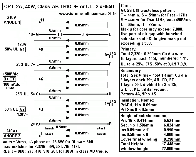
32. OPT-2A details for core, bobbin wire, insulation.
Fig 3. OPT-2A, for PP AB1 TRIODE ( or possible UL ) with 2 x 6550, KT88, KT90, KT120, 300B.
OPT-2A-40W-8k0-2r3-4r0-9r0-20r-PP-triode-UL.GIF
OPT-2A has T 44mm x S 51mm for adequate LF response with triode with Ea up to +500Vdc for a pair of
6550, KT88, KT90, KT120. It is a "simple OPT" to suit triode use up to 50W, but UL operation is easily
possible to get Po up to 75W from anodes. The purpose of this OPT is for Hi-Fi, and to be able to enjoy
mainly class A performance even with 4r0 speakers. Using 4r0 connected to OPT strapped for 2r3, the RLa-a
= 13k4, where the first 16W are pure class A where Iadc = 50mA per tube.

Back to
PP OPT Page 4

PP OPT Calc Page 3

PP OPT Calc Page 3A

PP OPT Calc Page 2

PP OPT Calc Page 1

Index