PP OPT CALCULATIONS PAGE 3.

Design of OPT-1A continued,
Steps 23 to 38, continuing on from Page 2,

So far, Core = T44 x S62mm, Np = 2,320t, wire = 0.355mm Cu dia, RwP = 117r, Primary winding
loss = 1.45% with nominal RLa-a = 8k0. Primary turns per layer = 145t for 16 primary layers.
Fsat = 14.1Hz at 632Va-a, 1.6Tesla.

23. Choosing the Primary and Secondary interleaving pattern may entirely bamboozle many readers
or designers without any experience of winding or analysing audio frequency transformers where
bandwidth from 14Hz to at least 70kHz is required. To achieve wide bandwidth the primary and
secondary winding sections must be interleaved, ie, alternately and evenly sequenced as the bobbin
is wound to its full height, so that the primary winding is effectively placed close to the secondary
winding for the length of the windings. Such interleaving can achieve a flat HF response which may
exceed 200kHz. 200kHz is rarely ever seen in most OPTs in mass produced amps because the
interleaving is minimal, say 3 Pri sections with 2 Sec sections.
But where there may be 5 Pri sections and 6 Sec sections, the HF response can extend to 270kHz.

There are NO FORMULAS which allow a designer or a DIYer to enter all parameters known for any
OPT to get one of many possible interleaving patterns.

I have prepared Tables 2, 3,4,5, below to allow the designer to select a possible interleaving pattern
based on the maximum power rating for the OPT, and number of P winding layers.
For OPT-1A, Power = 75W, 16 P layers. See Table 4.

Tables 2 to 5.......

TABLE 2.
OPT
Power
Total Pri
layers
Primary and Secondary
layer distribution.
P&S
section
pattern
0 to 7W 10p to 24p S - 10p~24p - S 2S + 1P
7W to 15W 10p to 20p S - 5p~10p - S - 5p~10p - S 3S + 2P
7W to 15W 10p to 20p 2p~4p - S - 4p~8p - S - 4p~8p - S - 2p~4p 3S + 4P


TABLE 3.
OPT
Power
Total
Pri
layers
Primary and Secondary
layer distribution.
P&S
section
pattern
15W to 35W 12p 2p - S - 4p - S - 4p - S - 2p 3S + 4P

12p S - 4p - S - 4p - S - 4p - S 4S + 3P

14p 2p - S - 3p - S - 4p - S - 3p - S - 2p 3S + 4P

14p S - 5p - S - 4p - S - 5p - S 4S + 3P

16p 3p - S - 5p - S - 5p - S - 3p 3S + 4P

16p S - 4p - S - 4p - S - 4p - S - 4p - S 5S + 4P

16p 2p - S - 4p - S - 4p - S - 4p - S - 2p 4S + 5P

18p 3p - S - 6p - S - 6p - S - 3p 3S + 4P

18p S - 4p - S - 5p - S - 5p - S - 4p - S 5S + 4P

20p 3p - S - 7p - S - 7p - S - 3p 4S + 3P

20p S - 5p - S - 5p - S - 5p - S - 5p - S 5S + 4P

20p 2p - S - 5p - S - 6p - S - 5p - S - 2p 4S + 5P


TABLE 4.
OPT
Power
Total P layers Primary and Secondary
layer distribution.
P&S
section
pattern
35W to 120W 14 p S - 3p - S - 4p - S - 4p - S - 3p - S 5S + 4P

14p
2p - S - 3p - S - 4p - S - 3p - S - 2p 4S + 5P

16p
S - 4p - S - 4p - S - 4p - S - 4p - S 5S + 4P

16 p 2p - S - 4p - S - 4p - S - 4p - S - 2p 4S + 5P

18p S - 4p - S - 5p - S - 5p - S - 4p - S
5S + 4P

18p
2p - S - 5p - S - 4p - S - 5p - S - 2p 4S + 5P

20 p S - 5p - S - 5p - S - 5p - S - 5p - S 5S + 4P

20p
2p - S - 5p - S - 6p - S - 5p - S - 2p 
4S + 5P

22 p S - 5p - S - 6p - S - 6p - S - 5p - S
5S + 4P

22p
2p - S - 6p - S - 6p - S - 6p - S - 2p 4S + 5P


TABLE 5.
OPT
Power
Total P
layers
Primary and Secondary
layer distribution.
P&S
section
pattern
120W to 500W 10p 2p - S - 2p - S - 2p - S - 2p - S - 2p 4S + 5P

10p S - 2p - S - 3p - S - 3p - S - 2p - S 5S + 4P

10p 1p - S - 2p - S - 2p - S - 2p - S - 2p - S - 1p 5S + 6P

10p S - 2p - S - 2p - S - 2p - S - 2p - S - 2p - S 6S + 5P

12p 2p - S - 3p - S - 2p - S - 3p - S - 2p 4S + 5P

12p S - 3p - S - 3p - S - 3p - S - 3p - S 5S + 4P

12p 1p - S - 2p - S - 3p - S - 3p - S - 2p - S - 1p 5S + 6P

12p S - 2p - S - 3p - S - 2p - S - 3p - S - 2p - S 6S + 5P

12p
S - 2p - S - 2p - S - 4p - S - 2p - S - 2p - S 6S + 5P

14p
2p - S - 3p - S - 4p - S - 3p - S - 2p 5S + 5P

14p S - 3p - S - 4p - S - 4p - S - 3p - S 5S + 4P

14p 1p - S - 3p - S - 3p - S - 3p - S - 3p - S - 1p 5S + 6P

14p S - 2p - S - 3p - S - 4p - S - 3p - S - 2p - S 6S + 5P

16p 2p - S - 4p - S - 4p - S - 4p - S - 2p
4S + 5P

16p S - 4p - S - 4p - S - 4p - S - 4p - S 5S + 4P

16p 2p - S - 3p - S - 3p - S - 3p - S - 3p - S - 2p 5S + 6P

16p S - 3p - S - 3p - S - 4p - S - 3p - S - 3p - S
6S + 5P

18p 2p - S - 5p - S - 4p - S - 5p - S - 2p
4S + 5P

18p S - 5p - S - 4p - S - 4p - S - 5p - S
5S + 4P

18p 2p - S - 4p - S - 3p - S - 3p - S - 4p - S - 2p 5S + 6P

18p S - 3p - S - 4p - S - 4p - S - 4p - S - 3p - S  6S + 5P

20p 3p - S - 5p - S - 4p - S - 5p - S - 3p 4S + 5P

20p S - 5p - S - 5p - S - 5p - S - 5p - S 5S + 4P

20p 2p - S - 4p - S - 4p - S - 4p - S - 4p - S - 2p 5S + 6P

20p S - 4p - S - 4p - S - 4p - S - 4p - S - 4p - S
6S + 5P

22p 3p - S - 5p - S - 6p - S - 5p - S - 3p 4S + 5P

22p S - 5p - S - 6p - S - 6p - S - 5p - S 5S + 4P

22p 2p - S - 5p - S - 4p - S - 4p - S - 5p - S - 2p
5S + 6P

22p S - 4p - S - 6p - S - 4p - S - 6p - S - 4p - S
6S + 5P

23. Continued....
From Table 4, for 16 primary layers, select P+S interleaving pattern of 4S + 5P or 5S + 4P.

4S + 5P has layer sequence in bobbin = 2p - S - 4p - S - 4p - S - 4p - S - 2p where each "p" is a
primary layer. "2p" is a Primary Section with two layers. "4p" is another Primary Section with 4 layers.
S is a Secondary Section, usually with one layer of wire much thicker than each primary layer.
The secondary sections may be sub-divided into 2, 3, or 4 windings to allow connections with other
secondary sections to gain load matches for 4r0, 8r0, 16r0 with equal leakage inductance and HF
response, equal winding loss % and ac current density equal in each winding, and while using all
secondary turns available.

The unequal number of P layers in each primary section occur to get best HF response with
leakage inductance occurring evenly and symmetrically distributed throughout the height of winding.
Where the first and last winding section wound on is for Primary, these sections should have
approximately 1/2 the layers of the inner primary sections. The inner P sections usually have equal
layers, but the number of layers may vary +/-33%. If there were a total of 18 P layers, inner P
sections have 4p and 5p, and the S sections cannot have equal layers.

All Push Pull OPT designed here using my methods should display adequate magnetic coupling
between the two halves of primary winding because each half is well coupled to the secondary.
This avoids a serious problem with distortion due to current cut off in tubes in class AB. ( This was
a problem in 1930's before anyone knew how to interleave P & S which cost more to do properly. )

As the number of P+S sections are increased, the leakage inductance reduces, with minimum LL
where there are equal number of layers for P and S windings, each interleaved S-p-S-p-S-p-S-p-S etc.
While having low LL is good to obtain good HF response, the shunt capacitance increases with the
many P to S interfaces, and the number of insulation layers prevents the required amount of copper
in the bobbin to get enough turns. The tables 2,3,4,5 offer interleaving patterns which reduce LL
adequately, and keep shunt C adequately low so that resonance between LL and shunt C occurs
well above 70kHz where resonance can be damped by R+C Zobel networks without affecting the
amplifier performance below 20 kHz. For lower Primary RL and higher amplifier power the OPT
becomes larger and interleaved P and S sections are increased because LL must be made low to
suit lower loads. With lower loads the capacitance has less effect. So a small 15W OPT may only
need 3S + 2P sections for 70kHz, but a 400W OPT may need 6S + 5P sections.

23. For OPT-1A, Confirm interleaving pattern = 2p - S - 4p - S - 4p - S - 4p - S - 2p = 4S + 5P.

24. Choose insulation thicknesses from Table 6.
0.05mm insulation is used between primary layers to lessen possibility of shorted turns even where
the layers  have similar Vac and Vdc, and to facilitate winding with small diameter wire.

Where there is large Vdc or Vac difference between any wire layers or between wire and core
the insulation should be thick enough to avoid insulation breakdown and arcing. Most modern
plastic film sheets like polyester have high enough voltage breakdown ratings to prevent any
problem in any OPT with Vdc up to +1,500V and Vac adding to peak volts across insulation
up to 3,000V.
Insulation is not chosen only for its breakdown voltage rating but for its thickness to reduce
shunt capacitance. 

I see no reason why Nomex insulation could not be used for OPTs.
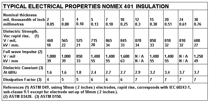
The data for Nomex 401 electrical grade paper is here :-
http://www.dupont.com/content/dam/assets/products-and-services/electronic-electrical-materials/assets/DPP_Nomex410_K20612-1.pdf

Table 6. About Nomex 401.
Re-typed-nomex-401-ratings-table.GIF
The lowest V rating values are for V / mil, ie, voltage rating per 0.001 inch, or 0.025mm.
Voltage rating varies between lowest at 460V / mil for 0.05mm thickness and highest
at 870V / mil for 0.3mm thickness.

From what the Nomex table shows, V ratings for thicknesses may be tabled :-
Table 7.
Nomex
insulation
Volts / 0.025mm
rating
Volts for
thickness
0.05mm
460
920V
0.1mm
525
2,100V
0.18mm
865
6,228V
0.25mm
845
8,450V
0.3mm
870
10,440V
0.38mm
850
12,920V
0.51mm
810
16,524V
0.61mm
810
19,764V
0.76mm
680
20,672V
The Nomex table information does not show a linear increase in Volts / mil for thickness but
there should be no worry about insulation thickness not having high enough V ratings
for any OPTs designed by methods at this website.

Before 2017, the insulation table at output-trans-PP-calc-5.html for minimum insulation
thickness was used for all designs at this website. The table lists much thicker insulation
than in the Nomex table for Volts. But this meant Shunt C was minimised.

NOTE. Insulation may be thicker than the minimum selected to achieve lower shunt C
to extend HF response and reduce phase shift for above 10kHz to make stabilisation with
NFB easier and more reliable, especially where RLa-a is between 10k0 and 30k0.

For OPT-1A, Calculate probable peak Vac + Vdc between P and S winding layers :-
500Vdc plus 500Vac peak swing = 1,000V. 0.1mm insulation thickness would be OK but
for low shunt C use 0.38mm or 2 layers of 0.25mm for 0.5mm.

NOTE. With no secondary load present, and high signal input to amp with pure tetrode or
pentode mode the total Vdc + Vac peak swing may exceed +/- 2,000V at each anode due to
energy stored in leakage inductance with no R load to shunt it, or without clamping diodes
between each anode and 0V to limit negative going Vpk to 0V, and hence limit positive going
Va peak to twice Ea.
However, arcing is unlikely unless excessive Vac is maintained for a long time, or there
moisture or pollution present or if poor insulation material is used.
I have seen old OPTs which used plain waxed paper insulation and some arced between
wire leads to windings with less than 350Vdc, because of accumulated grime and moisture
and cracked enamel where wire was bent. In one case I was able to clean away the dirt,
dry it out, and paint on electrical vanish and it never arced again. But arcing can occur inside
a poorly insulated OPT and nobody can repair it.
Varnishing should improve the insulation resistance. Insulation should be polyester or Nomex.

I do not favour Kraft electrical paper. Its dielectric constant may be like Nomex but afaik, the
dielectric constant increases when paper is soaked with varnish and baked, making
shunt C
higher. For PTs which operate at 50Hz, the shunt C is no problem and electrical grade paper
and cardboard or "elephantide" is fine.

25. Draw basic interleaving pattern.
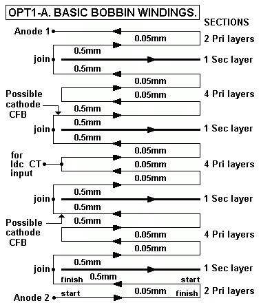
Fig 1. Basic interleaving.
OPT-1A-basic-interleave-sketch.GIF
Fig 1 shows basic interleaving pattern for bobbin winding layers chosen so far, and the
diagram represents the build up of concentric layers from the bottom of a bobbin, with
traversing direction alternating for every primary layer. All secondaries are wound with
the same traverse direction.

Primary layers begin at Anode 2, and winding layers traverse across bobbin as arrows show.
The bottom primary section has two layers with entry and exit wires brought out 150mm to a
temporary hold point on lathe chuck, and each wire is labelled with masking tape and a number.
Secondary entry and exit wires are 150mm long and labelled with tape with letters. Varnish
which dries slowly is brushed on to all wire layer and and insulation layer surfaces during
winding if there is no way to have windings varnished with vacuum impregnation after winding
is complete.

Your first drawing of the contents in a bobbin may be a much less tidy pencil sketch on a sheet in
a notebook, but it must tidy to avoid confusion or a mistake.

For OPT-1A :-
For Pri to Pri, with consecutive anode layers where V difference < 100V, shunt C is not a
problem use 9 x 0.05mm insulation which will make winding easier.

For Pri to Pri, with anode and cathode layers with Vdc + Vac difference = 1,000V, use 0.5mm
or 0.38mm if total winding height is found to be too high. Allow for 2 insulation layers x 0.5mm.

For all Pri to Sec interfaces where total V > 1,000V, use 8 x 0.5mm.

Total thickness of all insulation = 9 x 0.05mm = 0.45mm + 10 x 0.5mm = 5.0mm = 5.45mm.

26. Calculate height of Primary and all insulation = 16 Pri layers x 0.414mm oa dia = 6.624mm.
Height of all insulation layers = 5.45mm.
Total height of Primary + all Insulation = 6.624 + 5.45mm = 12.074mm.

27. Calculate max theoretical oa dia of Secondary Wire.
Calculate available height for layers of secondary wire :-
Available Sec height = ( Available height in bobbin ) - ( Height P + all Insulation ).
Available height in Bobbin = 0.8 x H window dimension.
OPT-1A, Available bobbin height = 0.8 x 22mm = 17.6mm.

Height of all secondary wire layers
= Available bobbin height - ( height of all insulation + primary wire layers )
= 17.6mm - 12.074mm (from Step 33) = 5.526mm.

Max Theoretical Sec oa dia = ( Avail Sec height ) / no of  S sections one layer each
= 5.526mm / 4 = 1.381mm.

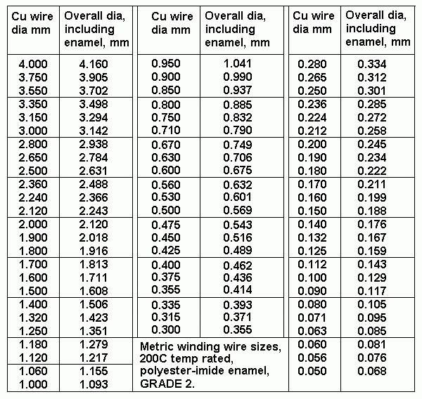
28. Choose maximum wire size from Table 8 with oa dia less than maximum in step 34.
Try 1.351mm o/a dia wire, Copper dia = 1.25mm.
Table 8. Wire sizes.
table-wire-sizes.gif
29. Calculate the theoretical Sec turns per layer with maximum wire oa dia.
Theoretical S turns per layer, th S tpl = bobbin winding width / max oa dia
= 62mm / 1.351 = 45.89 turns per layer. Omit fractions of a turn, th S tpl = 45tpl.

NOTE. These sec turns per layer are for the thickest wire possible. Sec layers should
be have any gaps between turns. 45t will fill the layer almost fully. Thicker sec wire
with less turns per layer should not be used if the height of all bobbin content exceeds
0.8 x Core H which may prevent insertion of core Es to a wound bobbin.

But Sec turns per layer may be increased up to +20% with smaller wire dia without
causing much increase of winding resistance to get a match to a higher load.
If 45t are a match for 3r0, then +20% = 54t which matches 4r3. But selection of smaller
wire size always reduces total secondary copper in bobbin and Sec Rw loss %
always increases.

30. Examine possible load match range for above Sec with 45t, 48t and 51t per layer.
Possible load matches are :-
Table 9. Load ratios for 2,320t : 45t, 48t, 51t.
Np =
2,320t
RLa-a
Ns = 45t,
ZR 2,658
Ns = 48t
ZR 2,336
Ns = 51t,
ZR 2,069
Class
A Po
Class
AB Po
4k0
1r5
1r7
1r9
5W 75W
6k0 2r3
2r6
2r9
7.5W 60W
8k0
3r0
3r4
3r9****
10W 50W
12k0
4r5
5r1
5r8
15W 35W
16k0
6r0
6r8
7r7
20W 24W
24k0
9r0
10r3
11r6
18W nil
If you read the table, and select RLa-a = 8k0, then Ns 45t gives 3r0, Ns 48t gives 3r4,
and Ns 51t gives 3r9.
Let us consider Ns = 51t, giving load match 8k0 : 3r9.

31. Overview of Sec load matches so far.
Best load match for most people for hi-fi will be with Sec = 51tpl which gives 8k0 : 3r9.

32. Calculate max oa dia sec wire for 51tpl = 62mm / 51 = 1.216mm. Choose wire from wire
table 7.
TRY 1.06mm Cu dia wire with oa dia = 1.155mm. These will fit on layer OK.

33. Calculate secondary winding resistance loss % for 4 parallel sec layers each 51t,
for load match 8k0 : 3r9.
Rws = S tpl x TL mm / ( 44,000 x No of parallel windings x Cu dia squared ) ohms,
where 44,000 is constant = ( resistance 100M wire 1.0mm dia / 100,000mm ),
TL = turn length mm, and Cu dia is for sec wire.
Rws = 51t x 281mm / ( 44,000 x 4 x 1.06mm x 1.06mm ) = 0.072r.
Sec Rw loss % = 100% x 0.072 / 3.972 = 1.8%, < 3% = OK. At RLa-a = 4k0, Sec = 2r0,
and sec Rw loss = 3.47%. This is slightly above 3%, but it may be OK.  

34. Calculate total P + S loss %, for class A with RLa-a = 8k0. From a previous step,
P loss % = 1.44%.
From step 33, Sec loss with Ns = 51t for 3r9 is 1.8%. Total P+S loss % = 1.44% + 1.8%
= 3.24%,
close to 3%, OK. For maximum Po with some class AB Po, the total loss may increase to 4%.

35. Calculate total P + S loss % for maximum class AB Po with RLa-a = 4k0.
With RLa-a = 4k0, there is a small amount of initial class A where the total P+S loss %
= 2.84% + 3.47% = 6.31%, < 7% = OK.

Most of the maximum power delivered to 4k0 is class AB.
Where the calculated RwP loss % is nearly equal RwS loss % for class A operation, and for
where the OPT is used for maximum class AB operation where little class A Po is produced,
and where RLa-a = 4k0 for Po > 70W class AB, the effective total Rw losses increase by factor
of 1.4.

Therefore, total loss for over 70W in class AB = 1.4 x 6.31% = 8.8%, and less than 10% which
is considered OK for when the amp is working as hard as it ever is expected.
 
Selection of Secondary sub-sections for range of wasteless load matches.

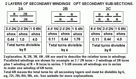
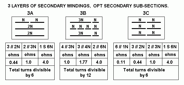
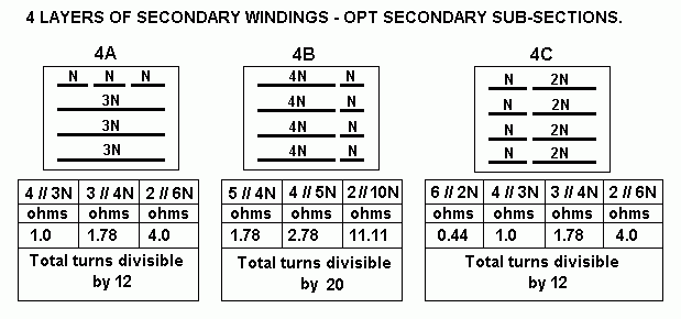
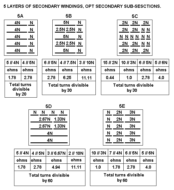
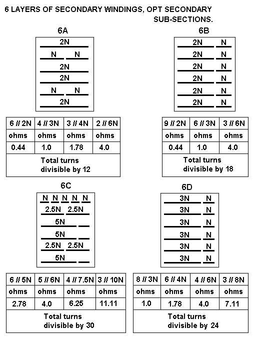
36. Examine Fig 2, 3, 4, 5, 6 for more load matches using patterns of Secondary Winding Sub Sections.
We have 4 Sec layers. Choose Fig 4 for sub section patterns.

Fig 2. For 2 sec layers........
opt-sec-2ABC-sub-sectionsX.GIF

Fig 3, For 3 Sec layers.
opt-sec-3ABC-sub-sectionsX.GIF

Fig 4. For 4 Sec layers.
opt-sec-4ABC-sub-sectionsX.GIF

Fig 5. For 5 Sec Layers.
opt-sec-5ABCDE-sub-sectionsX.GIF

Fig 6. For 6 Sec Layers.
opt-sec-6ABCD-sub-sectionsX.GIF
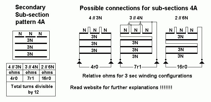
36 continued....Choose 4A from Fig 4, with 4 sec layers sections, with top layer section
divided into 3 sub-sections.
NOTE. A range of loads close to wanted 4r0, 8r0 and 16r0 is only possible if the total sec
turns are exactly divisible by 12, and turns in each layer are exactly divisible by 3.
For 51t per layer, it cab make 3 x 17t windings, and 4 layers gives 204t exactly divisible by 12. 

Examine Sec sub-section pattern 4A.
Fig 7. 4A sub-sections.
opt-sec-4A-sub-section-connectionsX.GIF
Fig 7 shows 4A pattern says "Total turns divisible by 12" so turns in each of 4 layers will
be exactly divisible by 3, or else the pattern will just not work properly.

Here is a list of total Sec turn numbers exactly divisible by 12 with the turns for 1 layer and
the load match to RLa-a 8k0 :-
156t = 39tpl = 2r3
168t = 42tpl = 2r6
180t = 45tpl = 3r0
192t = 48tpl = 3r4
204t = 51tpl = 3r9
216t = 54tpl = 4r3
228t = 57tpl = 4r8
240t = 60tpl = 5r3
We have already chosen Sec tpl = 51t for total of 204t.

37. List impedance matches available using chosen pattern 4A for Nominal Middle RLa-a = 8k0.
Table 9. 4A. Np = 2,320t,
Ns = 51t, using 4 parallel x 51t = 3r9.
Ns = 68t, using 3 parallel x ( 51t+17t ) = 6r9.
Ns = 102t, using 2 parallel x ( 51t + 51t ) for 15r5.

Pattern 4A gives THREE useful load matches to RLa-a 8k0. Each load match covers the load
variation for the average or nominal Z found in many manufactured speakers. For example,
a "4r0" speaker may have minimum Z = 2r5 and maximum 20r0. When used with sec = 51t,
RLa-a load varies between 5k2 and 41k4. The amp will handle the load change OK.
Giving the tubes the best load match right minimizes the bad effects of speaker Z variation, ie,
minimizes THD and IMD. But with only 3 possible load matches, if someone wanted only pure
class A operation with 4r0 speakers, they would be disappointed because the ratio of 8k0 : 3r9
is the highest available, and to get the ratio should be about 16k0 : 3r9, and this means Ns
would have to be lower and about 0.71 x 51t.
The other disadvantage may be that there is no perfect way to get 70W class AB for 16r0
speakers. We would want OPT ZR = 4k0 : 16, which means TR = 15.8 : 1, so Ns would
have to be 147t. However, with 4 sec windings of 51t each, the central 2 could be paralleled
and then connected in series to each of the other 2 x 51t to give Ns = 143t, which gives load
ratio = 4k0 : 17r4, so that high Po would be possible for 16r0 speakers. But I have NEVER
known anyone wanting high Po for 16r0 speakers so being able to strap the OPT for high Po
to 16r0 or even to include provision for 16r0 load match is probably never ever going to be
needed.

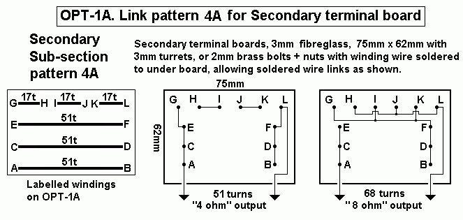
Fig 8. 4A strapping pattern.
OPT-1A-terminal-4A-board.gif
The strapping pattern for 16r0 is not included because it is unlikely to be used, but feel
welcome to figure out the strapping for 16r0.

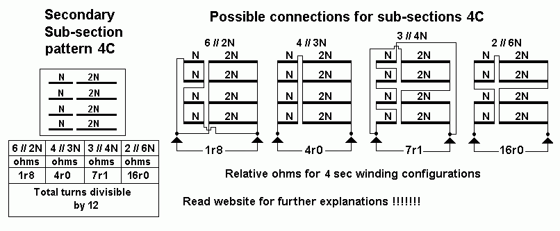
Examine Sec sub-section pattern 4C.

38. Let us consider using pattern 4C from Fig 4,
Fig 9. 4C sub sections.
opt-sec-4C-sub-section-connectionsX.GIF
Fig 9 Pattern 4C gives six useful load matches with 51t per layer with each subdivided to 17t + 34t.
5 load matches have equal current density with one for Ns = 153t with unequal current density.
All will work OK.

There are plenty of good load matches for everyone !

Table 10.
Np = 2,320t,
RLa-a
Ns =
6 //34t
ZR 4,656
Ns =
4 // 51t
ZR  2,069
Ns =
3 // 68t
ZR 1,164
Ns =
2 // 102t
ZR  517
NS = 3 x 51t
= 153t,
ZR 230
NS = 4 x 51t
= 204t,
ZR 129.3
Class  AB
power
Class A
power
4k0 0r86 1r9 3r4** 7r7**** 17r4
30r9
75W 5W
6k0 1r3 2r9 5r1 11r6 26r0
46r4
60W 7.5W
8k0 1r7 3r9** 6r9**** 15r4 43r8
61r9
50W 10W
12k0 2r6 5r8 10r3 23r2 52r2
92r8
35W 15W
16k0 3r4** 7r8**** 13r7 30r9 69r6
123r7
24W 20W
24k0 5r1 11r6 20r6 46r4 104r3
185r6
nil 18W
Table 10 gives 5 useful matches allowing over 70W to any sec load between 0.9r and 185r,
with Ns = 34t, 51t, 68t 102t and 153t.
The Ns = 153t has 2 central 51t in parallel, and is in series with 2 x 51t, and allows high class
AB Po for 16r0 speakers. The Ns = 204t has 4 x 51t sec layers in series, and would suit
powering a line array speaker with many drivers in series, or it could power a 100V line to
deliver about 30W to a number of remote speakers fitted with step down transformers.

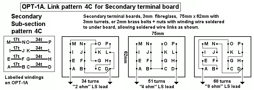
NOTE. The pattern 4C from Fig 4 will require 16 terminals for the secondary windings to be
set out on a terminal board to allow soldered wire links of the terminals in 4 different patterns
to achieve the desired load matching. Many audiophiles would be confused with making a
load match change so they would need a technician to make sure the load match change is
done correctly. If a mistake is made with strapping terminals differently, it could damage the
amp, or give very poor music.

Fig 10. 4C board terminals.
opt-1A-terminal-4C-board.gif
Fig 9 is terminal board for 4C link patterns for nominal 8k0 : 2r0, 4r0 and 8r0.
The real loads with RLa-a 8k0 are in fact for 1r7, 3r9, 6r9, but this allows for the minimum Z
of any speaker being lower than its nominal value. These selections will suit those wanting the
most pure class A. There is no strapping pattern for 16r0 speakers because they are unlikely
to be used, but will work OK with "8r0" outlet.

Forward to
PP OPT Calcs 3A

PP OPT Calcs 4

Back to
PP OPT Calcs 2

PP OPT Calcs 1

Index