PP OPT CALCULATIONS PAGE 3A.

OPT-1A. Steps 39 to 50.
General notes at bottom.

So far, OPT-1A Core = T44 x S62mm, Np = 2,320t, wire = 0.355mm Cu dia, RwP = 117r, Primary
winding loss = 1.44% with nominal RLa-a = 8k0.
Primary turns per layer = 145t for 16 primary layers. Fsat = 14.1Hz at 632Va-a, 1.6Tesla.
Secondary = 4 layers each 51t, 1,06mm Cu dia, one layer = 3 x 17t wound trifilar.
RwS for 4 // 51t = 0.072r gives Sec loss = 1.8%.


ALTERNATIVE SINGLE SECONDARY FOR ALL SPEAKERS ABOVE 4r0.

39. If the amp is to be only used with speaker loads above 4r0, and there are no demands
for high class A Po, the secondary may be configured to give only ONE load match, and
it will be for the Middle primary RLa-a 8k0 and secondary between 5r0 and 6r0, say 5r0.
It is usually impossible to get an exact load ratio of exactly 8k0 : 5r0, 1.600 : 1.0.
Turns per layer are determined by layer filling, winding losses, and wire sizes, but usually a ZR
giving 8k0 : 4r7 to 5r6 will do, so TR may be between 42 and 38 to 1.0. To achieve this,
subdivided sec windings are used, but once links are soldered there will be no need to ever
alter the OPT link settings.

Table 1. OPT-1A, possible load matches for single sec links.
Pri 2,320t
RLa-a
Sec 51tpl,
4 // 51t,   3 // 68t

Sec 54tpl,
4 // 54t,   3 // 72t
Sec 57tpl,
4 // 57t,   3 // 76t
Sec 60tpl,
4 // 60t,  3 // 80t
8k0
3r9     
6r9 4r3    
7r7 4r8****
8r6 5r4****
9r5
7k0
3r4
6r0 3r8
6r7 4r2
3r7 4r7****
8r3
6k0
2r9
5r2**** 3r2
5r8 3r6
6r5 4r0
7r1
5k0
2r4
4r3 2r7
4r8**** 3r0
5r4**** 3r4&
5r9
4k0
1r9
3r4 2r2
3r9 2r4
4r3 2r7
4r7****
This table shows **** at each best single sec arrangement to suit all RL > 4r0.
The tubes used would be 2 x KT88 and have about same idle Pda but lower Ea for each RLa-a shown.
If you used the original OPT-1A design with 4 x 51tpl secs, then Ns = 3 // 68t will give 6k0 : 5r2.
Where the tubes have lower Ea to suit 6k0, There is fair performance for all speakers above 4r0.

But for OPT-1A with 4 x 57tpl secs, then Ns = 4 // 57t gives 8k0 : 4r8, and suits all speakers above 4r0.

57t of 1.0mm Cu dia with 1.093mm oa dia should fit on plastic bobbin with distance between cheeks
slightly more than theoretical 62.0mm for window 22mm x 66mm.

Sec RwS with 57tpl with Cu dia 1.00mm = 57t x 281t / ( 44,000 x 4 x 1.0mm x 1.0mm ) = 0.0904r.
For sec RL = 4r8, Sec Loss % = 100% x 0. 09r / 4.89r = 1.8%.
Rwp = 1.44% for RLa-a 8k0, total P + S loss = 3.24%, quite acceptable.
For 4k0 : 2r4 load, total P+S loss = 2.84 % + 3.24% = 6.08% and < 7% = OK.
---------------------------------------------------------------------------------------------------------------------------------
OPT-1A with Np 2,320t and Ns = 4 x 51tpl continued....
40. Draw sketch of winding layer details.
Those who wind an OPT will need ALL THE INFORMATION on one page to avoid confusion,
guesswork and mistakes.

Previously in PP calc 3 it was calculated that ideal sec for 3 adjustable loads was 51t per layer
giving 8k0 : 3r9, 6r9, 15r6.

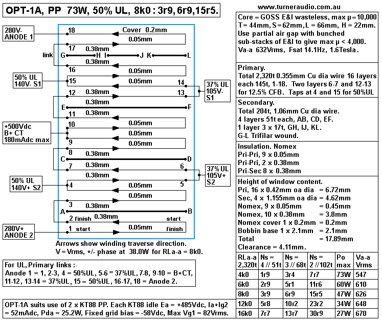
Fig 1. OPT-1A for UL or triode or beam tetrode, pentode ( and possible CFB ).
OPT-1A-73W-UL-8k0-4r-7r-15r-bobbin.GIF
Fig 1 has my preferred 50% UL taps, also found in Leak amps. Mullard said 43% was the correct %.
RCA used 30%. There is no strict rule for UL tap % which should be between say 35% and 55% to be
most effective at reducing 6550 beam tetrode Ra from a typical 33k at Ia 50mAdc, down to about 2k2
at 50% UL taps. I have used 60% UL taps for 6550 which reduces Ra to about 2k0, and allows 45W
AB of beam tetrode power with RLa-a 8k0.

The B+ = Ea = +500Vdc, and this is what I regard as maximum for UL with 6550, KT88, KT90, KT120.
Fixed bias is best. 

OPT-1A does allow for UL taps at 25%, 37.5%, 50%. The 50% UL THD is as low as triode for same initial
class A Po.

Table 2. OPT-1A, Triode KT88, 6550 etc Ea +500Vdc, Ia 50mAdc ea.
RLa-a
2,320t
Ns
4 // 51t
Ns
3 // 68t
Ns
2 // 102t
Po
Max
Va-a
Vrms
4k0
1r9
3r4
7r7
40W
410
6k0
2r9
5r1
11r6
34W
466
8k0
3r9
6r9
15r5
29W
494
16k0
7r7
13r7
30r9
21W
580

OPT-1A gives higher amount of class A in all modes with Ea +400Vdc, and KT120 allows Ia = 87mAdc.
Alternatively, use of 4 x EL34, each with Ia 50mAdc also gives splendid class A operation.
With lower Ea, the maximum Class AB for UL is about 50W for 4k0.

41.
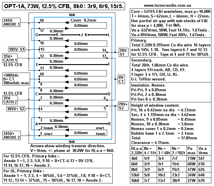
Fig 2. OPT-1A for 12.5% CFB ( and possible UL ).
OPT-1A-73W-CFB-8k0-4r-7r-15r-bobbin.gif
Fig 2 shows OPT1A with two primary layers 6-7 and 12-13 used for 12.5% CFB windings.
The 12.5% means that 2 primary layers of a total 16 layers will give Vac at cathode
= 12.5% of total Vac between anode and cathode. This Cathode Feedback alone will reduce
tetrode tube Ra to less than any use of UL taps. However, the screens may be connected to
primary taps at 5 and 14 where there is 70Vrms- where Va = 245Vrms-, and Vk-0V = 35Vrms+.
Therefore Vg2-k = 90Vrms-, and the tube has 37.5% UL taps but also has the 12.5% CFB.
The result is a low gain output stage with very effective Ra but spectral content that is probably
best. UL taps to OPT will make Eg2 = Ea, and Eg1 needs greater -Vdc bias.
When I first built the 8585 amp in 1995 with Ea +400V and fixed bias and CFB and UL taps, and with a
similar OPT, and with 4 x GE6550A, I was able to get 50W AB and THD = 0.7% without any GNFB.

I later found that Ea could be increased to +480Vdc with screens taken to a fixed Eg2 rail at +330Vdc.
The increased Ea allowed bigger Va swing and with 4 x KT90 the amp could easily make 100W class AB.
But the first 20W is all important for hi-fi amps.

Table 3. 12.5% CFB allows Ea up to +700Vdc, with fixed Eg2 < 450Vdc, 2 x KT120.
La-a
2,320t
Ns
4 // 51t
Ns
3 // 68t
Ns
2 // 102t
Po
Max
Va-a
Vrms
4k0
1r9
3r4
7r7
160W
820
5k0
2r4
4r3
9r6
135W
848
6k0
2r9
5r1
11r6
121W
876
8k0
3r9+++
6r9+++
15r5+++
95W
898
12k0
5r8
10r3
23r2
72W
931
16k0
7r7
13r7
30r9
55W
939
I have placed +++ against load matches I might approve of. The output Po is what you should get
at Sec output, and you can see the Va-a is all above 820Vrms, severely dangerous.

See OPT-3A at bottom of this page for a slightly different OPT for high Ea.

It uses same core T44mm x S62mm and same primary winding but secondary has less turns of thicker
wire to get higher TR and ZR so suite the higher Va swing. I have never ever wanted to use any octal
based tubes with Ea higher than +500Vdc, and I think its always better to use a quad of tubes with lower
Ea than a pair of tubes with higher Ea. OPT-3A is for those poor souls who believe maximum Power is
most important, even though they rarely ever use more than 2W of average Po from their amps. 

42. OPT-1A, Calculate total Bobbin content height for both Fig 10 and Fig 11.
Primary 2,320t 0.355mm Cu dia, Secondary 204t, 4 x 51t layers, 1.06mm Cu dia.
Primary wire layers, 16 x 0.42mm............................6.72mm.
0.05mm insulation, p to p layers, 9 x 0.05mm..........0.45mm.
0.38mm Insulation, p to p layers, 2 x 0.38mm..........0.76mm.
0.5mm Insulation p to S layers, 8 x 0.38mm ............3.04mm.
Secondary wire layers, 4 x 1.155mm.......................4.62mm.
0.2mm Insulation wound over last on P layer...........0.20mm.
Bobbin base thickness.............................................2.1mm.
Total winding height including bobbin base............17.89mm.
Clearance from core = H 22mm = 18.894mm = 4.11mm = OK.

Notice OPT-A has 0.38mm Nomex insulation between 8 P-S interfaces and 2 P-P interfaces
between anode and cathode windings with 500Vdc difference.
Previously, I specified 0.5mm polyester, but nearest Nomex size is 0.51mm and 0.38mm is nearest
size below 0.5mm to allow easy winding without having to cramp the wound bobbin when
winding is complete to avoid the bulge making it difficult to insert Es into the wound bobbin.

There is a slight increase of shunt capacitance insulation reduced from original 0.5mm to
0.38mm, but Nomex data shows dielectric constant is less for 0.38mm than for 0.51mm, so
shunt C increase is not alarming.
----------------------------------------------------------------------------------------------------------------------------
43. Fig 3 below was first drawn over 10 years ago. I have tidied it up and added more useful
information.

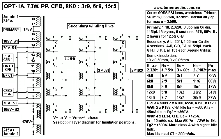
Fig 3. OPT-1A, Prim CFB links, Sec links.
OPT-1A-73W-CFB-8k0-4r-7r-15r-sec-links.gif
Fig 3 shows the same winding patterns as in Fig1 and Fig 2.

44. OPT-1A, Height of bobbin contents of OPT-1A was calculated in step 42 above.
The total height of all contents in the bobbin should not exceed 0.8 x core H size
= 0.8 x 22mm = 17.6mm. The listed heights above for bobbin content = 15.8mm, and the
bobbin base is estimated at 2.1mm thick so height of all things in window = 17.9mm.
But the cheeks of the bobbin extend higher than the bobbin contents so clearance between
top of wound content and core = 22mm - 17.9mm = 4.1mm. The wire will bulge at it is
wound around the rectangular core but it should be was to insert Es to bobbin window
without fowling cover insulation. Once Es and Is are assembled into wound bobbin and bolts
tightened pieces of phenolic sheet should be pushed into any gaps to prevent any movement.
Scrap kitchen bench covering 0.6mm thick is ideal, from a kitchen joiners rubbish bin.

In a number of OPTs I wound, I painted on slow curing epoxy varnish to every insulation
surface and winding layer liberally. At end of a day's winding I cramped the windings tight
with G-cramp and plywood squares while bobbin was still clamped between lathe clamps.
This forced excess epoxy out, or into voids unfilled, and it was left for a day or two until
the wound bobbin was quite solid.
This method usually gave me plenty of clearance to easily insert Es.

You need to fill the bobbin window efficiently, but not have wire and insulation too high
to work with.
-------------------------------------------------------------------------------------------------------------------
45. Core Permeability, µ.
µ is just a number, with no units. µ is used often and context MUST be remembered.
For transformer cores, µ is permeability or the core, but for a triode, µ is the amplification factor.

For an air cored coil, µ = 1.0, and very little different to the µ of the coil in a vacuum.
For an air cored coil, the magnetic field strength for a given ac or dc current below 1kHz is quite
low compared to the same coil with an iron core. So the air cored coil has much lower inductance
than the same coil, but fitted with an iron core. The iron cored coil may have many thousands of
times more inductance than an air cored coil. For a toroid core with a wound strip of thin GOSS
material, µ may be 40,000, ie, there is 40,000 times more inductance with GOSS core than
without it, roughly speaking. I don't have time for a page full of hideously complex equations about
each statement I make, but if buy an air cored speaker crossover coil of say 3mH, and add a bar
core taken from a fused PT, you should find the core measures 12mH, because the bar core aids
the production of stronger magnetic field and increases the inductance. Adding an iron core which
forms a continuous loop using overlapping laminations, the inductance may increase to 1,000mH.

GOSS or CRGO E+I, C-cores and other shapes of cores have maximum µ between about 5,000
and 17,000. The µ for GOSS has increased from 1947 when max µ was about 5,000 to maybe
17,000 in 2017, all due to changes made to rolling and heat treatments for the silicon steel.
Thus modern E+I or C-cores made after 1990 will usually have max µ > 10,000, and this means
the cores of PT do not get as hot as something made in 1937. It also means there is much less
distortion current produced in OPT transformers which are expected to work down to 20Hz.

However, there are strict limits for Vac level and Frequency because all metallic
cores are limited to their maximum field strength, Bac, which can be between 0.8Tesla and
2.5Tesla for exotic materials. GOSS usually may have max Bac = 1.6Tesla.

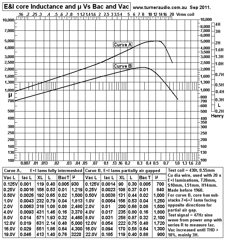
Graph 1. Core permeability of GOSS with max µ = 5,000.
graph-Lp-vs-Bac-Vac-nogap-partialgap.GIF
Graph 1 gives results of a test to plot the µ vs Bac for an old sample of GOSS E&I lams which may have
been similar to the core material used for the 1947 Williamson. The sample I have used here was taken
from a fused PT or OPT and was wasteless pattern E+I with T28mm. The lam thickness was 0.5mm.

The core sample for my test will not compare well with what you may find in OPTs made after 1980.
In 1950s, GOSS lams had max µ = 5,000, but I have used E+I lams made by Sankey in Australia in about
2001 with max µ = 17,000. The E+I power transformers I wound using this material barely got warm.
But at some time before 2010 Sankey closed their business due to plummeting demand caused by cheap
imports of transformers mainly from China where wages are 1/10 of any western nations and with
appalling work conditions.

The reason for drawing these graphs is to show what partial air gapping can do to reduced the max µ
to make a core for a PP amp less prone to Idc magnetization which may cause horrible sound is the net
Bdc for a PP core exceeds about 0.1Tesla due to the two output tubes having Idc difference exceeding
15%. Most GOSS E+I cores and C-cores may have max µ > 10,000 and the technical performance of the
core is better than it has to be, and very prone to Idc non balance in output tubes unless there is an Idc
balancing circuit with a pair of LED which should glow equally bright when balance is within +/- 5%.

I found the sample of old core I used would not like working with maximum intermeshing of lams above
0.7Tesla. Despite the max µ = 5,000, it occurs at 0.5Tesla, and for a PT this material would be useless
now if used with typical Bac 1.3T at 50Hz. In a PP OPT, this material would show signs of core saturation
at only 0.7T. It would be impossible to achieve a good OPT with Fsat 14Hz and you could only ever get
Fsat at about 32Hz with the design formulas at this website which is based on core material able to have
Bac max = 1.6T.

If you are going to make your own OPTs, and use old second hand cores, please test the material and
understand what you are doing. Don't ever blame me for the poor transformer performance if you have not
tested the core and you don't know what you are doing.

Reactance of inductance is the resistance of a coil at a known single frequency. The reactance XL
can be measured by measuring Vac across the coil and current flow in the coil, at say 50Hz and
XL = Vac / Iac.
Inductance, L = XL / ( 6.28 x F ), in Henry, where 6.28 = 2 x pye = 2 x 22 / 7, F in Hz.

Bac = 22.6 x Vac x 10,000 / ( Afe x N x F )
, where 22.6 and 10,000 are constants, Vac in
Vrms across coil, N is turns in coil, F is Hz.

µ = L x 1,000,000,000 x ML / ( 1.26 x N squared x Afe )
, where µ is permeability, L is inductance in Henry,
1,000,000,000 and 1.26 are constants, ML is iron magnetic path length mm, N is turns in coil, Afe is core
centre leg section area sq.mm = Tmm x Smm.

The graph above shows Vac applied at top, and inductance at left side.

For Curve A, the direction of E+I alternates for each consecutive E; this is known as maximum lamination
intermeshing aka interleaving, and it always gives the maximum possible µ for E+I lams.

For Curve B, to obtain results for "partial air gap", I re-arranged the laminations so E+I were divided into 3
sub-stacks each with 7 + 6 + 7 E+I lams, with the Es in each consecutive sub-stack facing the opposite
direction as the total stack was built up.

The results show the same applied Vac, and records the calculated Bac, XL, L and µ.

You can see the µ is not constant, and hence the inductance changes for different levels of Vac.
The L changes during each wave cycle, and the change of XL reactance causes distortion currents to be
created, mostly 3H, so XL must be kept high and well above the amp RL value , even at low Vac levels
where XL is lowest, and for low audio F. Most transformer cores are tested with mains F 50Hz or 60Hz,
and I used a sig gene with 47Hz and an audio amp.
Iron caused distortion is lowest for Bac < 0.32Tesla. µ may be highest where Bac is between 0.5T and 1.5T.

If Vrms is at maximum for coil, and Bac max = 1.6T at 14Hz, you have some good core material and the Bac
at 50Hz = 0.45T for the same Vrms and THD in bass music notes will be quite low.
--------------------------------------------------------------------------------------------------------------
DC MAGNETIZATION OF PP OPT CORES
PP OPTs have Idc input to a CT on primary winding and equal Idc flows in each 1/2 primary to each anode.
The direction of turns for the whole primary is the same but there is opposite direction of Idc flow direction
in each 1/2 primary so the Idc flows causes magnetizing fields which oppose one another so that there is
virtually no Idc magnetizing effect.
But where one Idc flow is more or less than the other, there is unequal Idc and the difference between the
two Idc can cause partial or total Idc magnetization of the core. In other words, the core becomes magnetized
like any electromagnet which is powered with Idc flow. For PP OPT, best signal operation with low THD is
achieved with equal Idc flows in each 1/2 primary, but in the real world there is always some slight inequality
so all PP OPTs do have some slight Idc magnetization, but it is benign, and won't affect the music at all
if Idc both tubes is high enough at say about 50mAdc, and the Idc difference is less than + / - 3mAdc.

The Idc magnetization of an iron cored coil = Bdc, and is calculated
Bdc = 12.6 x Idc x N x µ / ( 10,000 x ML )
, where 12.6, 10,000 are constants, N = turns, Idc is in Amps dc,
ML = magnetic path length of iron in mm, and Bdc is in Tesla.
But because the difference of Idc in each 1/2 primary winding causes the Idc magnetization of a winding
on iron core with CT,
 
Bdc for whole core = 12.6 x Difference of Idc in each 1/2 Pri x 0.5 x N x µ / ( 10,000 x ML.

The core Bdc cannot exceed about 1.6T for GOSS when it becomes fully magnetically saturated, so where
calculated Bdc > 1.6T, the real Bdc < 1.7T.
Where calculated Bdc > 1.6T, small changes to B due to Iac will make the coil behave as if it has no inductance
and as though has only wire resistance. Large Iac changes with high Bdc present will reduce total B below 1.6T
so that for part of the wave cycle the coil appears to have some inductance.

But for PP OPT, only low Bdc is wanted.

Idc difference between each Idc flow required for Idc saturation = 1.6T x 10,000 x ML / ( 12.6 x 0.5 x N x µ ).

For OPT-1A, if µ = 5,000, the Idc to saturate core = 1.6 x 10,000 x 245mm / ( 12.6 x 0.5 x 2,320t x 5,000 )
= 0.054Adc = 54mAdc. In the real world, if one of the two output KT88 does not conduct Idc, the core will
saturate fully, and the music will still be heard at low levels but the tube which is conducting is under duress
and if music level is turned up the sound is just horrible. 
If the core was a wound toroid of GOSS, its µ may be 40,000, and the Idc difference needed to saturate core
= 7mAdc, a small amount of Idc. I have often serviced amps where Iadc in one was say 45mAdc, and 55mAdc
in the other and this would cause full saturation of a toroid core, and I am not at all in favour of ever using a
toroid OPT core unless it had an air gap to reduce the max µ.

The core with µ = 5,000 could have Idc imbalance = 10mAdc, which might cause Bdc = 0.3Tesla, and and
although THD would increase, the amp would still work. I have used E&I with max µ = 17,000, much higher
than needed, but had active circuit to give Idc balance condition using two LED at front panel.
To calculate the Idc required for core saturation, the max µ value is used. But the µ varies with Idc or Iac flow
and Curve A above shows max µ = 5,000 but minimum µ is 1,000, so with a low Idc difference the Bdc will
be lower than calculation predicts.

I have found µ need not be higher than max 4,000 and if it is only 1,000 at very low Idc and Iac levels then
the Lp is still usually high enough to give XLp = RLa-a at below 20Hz.

If the use of  E&I sub-stacks reduces max µ to below 4,000, the the Idc imbalance is much better tolerated.

For best operation without Idc imbalance, there should be an adjustment pot to alter Eg1 grid bias -Vdc
for each tube and a circuit to drive a pair of LED used to indicate state of Idc balance, as I show in a
number of tube amp schematics.

With C-cores, the partial air gap is really a normal air gap, but it would be much smaller than for a Single
Ended OPT with a high Idc flow. In a 50W mosfet powered amp I built before 2000, I used C-cores for a PP
OPT and the µ max was about 5,000 max with cut surfaces tightly together. With a single layer of plastic
about 0.02mm thick, the µ max was reduced by 1/2, and the saturation behavior became much less likely
to cause excessive currents in the mosfets at very low F. Bass performance is excellent,
see solidstateamps4-50w-mono-mosfet.html

If all Es are just butted to all Is, and there is no real air gap, the change of grain direction in crystal
structure at each join of E to I acts like an air gap and a core with max µ of say 5,000 may have µ of only
900 when arranged as for an SE OPT, but with no gap. The low µ obtained this way is usually too low to
be able to get enough primary inductance. The sub-stack air gap can give the wanted max µ of say 4,000
by altering the number of Es and Is in each sub-stack. It is a tedious process to stack up Es and Is and
then change the sub-stacks and re-measure everything; it can take days. Automatic Idc balancing circuits
may not work well because they often become unstable with LF oscillations when GNFB is used.

46. OPT-1A. Calculate maximum and minimum primary inductance.
The minimum Lp is of greatest interest because its value affects how the tubes work at low F and the
stability of amp at LB with GNFB, especially where there is no Sec load connected and tube gain is
highest at low levels.

For most PP amps, if minimum Lp reactance XLp = RLa-a at 20Hz, then all is well, and as Va-a
increases above very low levels the µ rises to perhaps 3 times the low level value so the F where
XLp = RLa-a can move down from say 20Hz to 7Hz and inductance shunting effects become negligible.

Lp = 1.26 x N squared x T x S x µ / ( 1,000,000,000 x ML ) where Lp is Henry, 1.26 and 1,000
are constants, N is coil turns, T = Core Tmm, S = Core Smm, µ is for conditions of Vac, and F, and ML
= iron magnetic length in mm.

For OPT-1A, what is minimum Lp required? XLp = RLa-a 8k0 at 20Hz.
XLp = 6.28 x Lp Henry x Frequency.
Therefore min Lp = XLp / ( 6.28 x F ) = 8,000r / ( 6.28 x 20Hz )
= 63.7Henry. 

Now from above formula for Lp, where Lp is known, required µ can be calculated :-
µ = Lp x 1,000,000,000 x MLmm / ( 1.26 x Np squared x Tmm x Smm )
For OPT-1A, min µ = 63.7H x 1,000,000,000 x 245mm / ( 1.26 x 2,320t x 2,320t x 44mm x 62mm )
= 843.

The core µ is usually highest at lowest F. So if core µ = 843 at 20Hz, and very low Bac with Va-a = 5Vrms,
it should be found that at highest Va-a for say 50W for 8k0 at 20Hz, the µ will be close to high as it can go
with partial air gapping, say 3 x 843 = 2,529.
Therefore if the core with partial air gap has max µ = 4,000, it is highly unlikely the minimum µ will be less
than 843, because one effect of partial air gapping is to reduce the range of variability of µ.

Graph 1 shows Curve A, no partial air gap with max µ = 5,000, minimum = 1,000. Change factor = 0.2.
Curve B with partial air gap shows max µ = 2,100, minimum 700. Change factor = 0.33.

if modern core material with max µ 10,000 is used, partial air gapping may reduce max µ to 4,000 so
minimum µ = say 1,320.

The core could even be NOSS material, and it usually has max µ 3,500 with max intermeshing so there
is no need for partial air gapping and you may find there is always enough primary Lp to avoid load shunting
by Lp at low F.
I have used NOSS for 85W amps with 4 x KT88 per channel, with Afe = 44mm x 62mm and Np = 2,080t and
I had no problems during testing where Lp became too low at LF and a low level.

However, a LF gain shelving network is essential between V1 and V2 input / driver tubes to reduce open loop
gain below 20Hz. This always makes the amp recover quickly after excessive Vin is applied, and prevents
peaks in F response below 20Hz due to total phase shift becoming high enough to cause the peaking.

Mr Williamson said way back in 1947 that for RLa-a 10k0, minimum Lp should be 100H, so there should be
10H for each 1k0 of load, so
Minimum Lp = 10H x RLa-a / 1,000, where RLa-a = Nominal value, in ohms.
For OPT1A, Min Lp = 10H x 8,000 / 1,000 = 80Henry.
This is where the core µ will be minimum at say 50Hz. 

Using Unkel Willy's idea, required minimum µ for core for OPT-1A :-
µ = Minimum Lp x 1,000,000,000 x ML / ( 1.26 x N squared x T x S )
= 80H x 1,000 x 245mm / ( 1.26 x 2.32 x 2.32 x 44mm x 62mm ) = 1,059.
XLp = 8k0 at F = 15.9Hz,

This minimum core µ is easily reached with GOSS E+I or C-cores providing Np and
Afe are both large enough, and Afe > 300 x sq.rt Po.

The measured LF response and LF pole is never equal to where XLp = RLa-a because the tubes have Ra.
The -3dB pole for LF response is where XLp = ( load RLa-a parallel to tube Ra-a ).

Two KT88 tubes with 40% UL may have Ra-a = 5.6k, so 8k0 // 5k6 = 3k3, and if Lp = 80H,
then -3dB LF pole = 3,300 ( 6.28 x 80H ) = 6.6Hz, and this may be without any GNFB or gain shelving
network and at low levels to avoid core saturation, and the KT88 have grid Vg-g that has flat F response
with -3dB at below 4Hz. To explore VLF response, the coupling caps between V1-V2 and V2 to KT88 may
need increasing from 0.47uF to 1uF, and C at input increased.  

If 2 x KT88 were used in pure beam tetrode mode with fixed Eg2 and no CFB, then Ra-a might be 60k
at idle Idc.
Without any sec load, the -3dB F response pole is
where XLp = Ra-a = 60k, and -3dB is at 60,000 / ( 6.28 x 80H ) = 119Hz.

In triode mode, with Ra-a = 2k0, and no RLa-a, -3dB is at 4Hz.

I conclude the F response for any OPT relies on the "total terminating resistance"
across the primary or secondary which are nominal loads parallel to Vac source resistance.

47. Core Saturation. This was calculated in an earlier step, but I repeat :-
Fsat = 22.6 x V x 10,000 / ( S x T x Np x B ) where Bac is in Tesla, with 1 Tesla = 10,000 Gauss,
22.6 and 10,000 are constants for all transformer equations, V = Vrms across the primary,
or sq.rt ( Power x Primary RLa-a ), S = core stack height mm, T = core tongue width mm,
Np = primary turns,
F = frequency at which B is to be measured.

OPT-1A, For 50W into 8k0, Va-a = 632Vrms, Bac max = 1.6Tesla, S = 62mm, T = 44mm, Np = 2,320t,
Fsat = 22.6 x 632Vrms x 10,000 / ( 62mm x 44mm x 2,320t x 1.6T ) = 14.1Hz.

Core saturation occurs as a result of applied Vac and frequency across the inductance of coil, and the
onset of saturation above 1.2 Tesla is most clearly seen on an oscilloscope where no load is connected.

For OPT-1A, we would find Fsat 7Hz at Va-a = 316Vrms, and 3.5Hz at Va-a = 158Vrms. Most music
has very little content below 32Hz and bass signals cannot ever be at the maximum possible Va-a level
because there would be no headroom for all other musical frequencies. Therefore core saturation is
not a problem in most hi-fi amps even where the Fsat occurs at max Va-a at say 32Hz.

I have always preferred all my PP OPTs to saturate at 14Hz if possible because there is less bass
distortion and the bass is subjectively superior. The amp should have C+R network at input with pole
at say 7Hz to exclude stray signals with very low F. OPTs in amps can be tested using a pink noise
source. If the pink noise has bandwidth from 3Hz to 20kHz, and output Vo increased to where clipping
on peaks begins to occur, there can be an irregular knocking sound in OPT caused by occasional high
levels of LF causes intermittent core saturation. I found adding the 7Hz HPF minimised the saturation
at very LF. And the sobering fact is that where pink noise begins to clip, a Vac meter will show average
Vac level is 1/3 of peak level. Music signals are remarkably similar to pink noise but has some F present
that are harmonically related to others, and there are high average level changes, but as soon as
music Vac clips, you have reached maxim possible and average level is 1/3. This means that a 50W
amp happily makes 5W average, and if speakers are 88dB/W/M, 5W average gives 95dB SPL and
this is way above the 85dB level most ppl can tolerate for more than 1/2 an hour.

48. Calculate leakage inductance, LL.
The leakage inductance in written specifications is sometimes described as being "referred to the primary."
This means it is considered to be an inductance in series with the primary load looking into one end of
the primary with the other end grounded. But with a PP amp, there are two opposite phases applied
across Pri so there is 1/2 the total LL in series between each anode and OPT input. Typical good
values of this inductance would be 10mH for RLa-a = 10ka-a, ie, 1mH per 1k0 of RLa-a.

LL = 0.417 x Np squared x TL x [ ( 2 x n x c ) + a ] / ( 1,000,000,000 x n squared x b )
where LL = leakage inductance in Henry, 0.417 is a constant for all equations to work,
Np = primary turns,
TL = average turn length around bobbin = 2T + 2S + ( H x 22 / 7 )mm.
2 is a constant because there is an area at each end of a layer where leakage occurs,
n = number of dielectric gaps, ie, the concentric gaps between layers of P and S windings.
c = the dielectric gap, ie, the averaged distance between the copper wire surfaces of P and
S windings, a = height of the finished winding in the bobbin, b = the traverse width of the
winding across the bobbin.
Distances are all in mm!

For OPT-1A, with Nomex insulation = 0.38mm, and c = 0.67mm, TL = 88mm + 100mm + 69mm
= 257mm.
LL = 0.417 x 2,320t x 2,320t x 257mm x [ ( 2 x 8 x 0.67mm ) + 18.0mm ] / ( 1,000,000,000 x 8 x 8 x 62mm )
= 0.00416 Henry, say 4.2mH.

For OPT-1A, LL in series with whole primary = 4.2mH.
Is the leakage inductance low enough?

The ratio of LL to RL should be 1.6mH : 1k0 or higher ratio so that XLL = RLa-a at 100kHz or
higher where RLa-a is the lowest expected load.
OPT-1A. Lowest RLa-a expected = 4k0. LL = 4.2mH, XLL = lowest RLa-a at 152kHz = OK.

Where RLa-a is higher at say 8k0, XLL = RLa-a at 303kHz = OK.

49. Shunt capacitance of an OPT, C. Capacitance in a tube amp OPT is like having a perfect
OPT with no C and having a C across the primary. This C acts to reduce the primary load at HF in a
similar manner to how Lp reduces primary load at LF.

C exists between primary turns and between primary layers which all sum to what is called
"self capacitance" of a primary winding. For a 2,320t winding with no P+S interleaving, ie, with all Pri
turns together, possible self C = 500pF.
But with 5 P sections separated by 4 S sections, the self C of each P section may be < 100pF, but
because 5 pri sections 5 are in series, and well apart from each other, total self C = 20pF, and is a
negligible quantity.

The sectioned P winding is like an RF choke with 5 separated windings in series with mutually shared
inductance but winding has low self C so resonance of the RF coil is above the wanted RF band for
the coil.

But in all OPT there is a much larger C between Pri layers next to Sec layers and it must be minimized
by using thicker insulation than needed to prevent arcing between B+ and earthy sec.

The C between an anode connection and 0V depends on the Vac between P and S layers.
Where 2 wire layers have no Vac level or phase difference, there is is no capacitance. And where each
layer had the same Vac level but opposite phase, C is twice that for where one layer has Vac and the
other has none, or a negligible amount such as where one layer has 20 times Vac of other layer, as in
an OPT with primary Vac many times secondary Vac. Therefore Vac of sec may be ignored and sec
regarded as "earthy" and at 0V for shunt C calculations.

At each anode there is C between anode and 0V, Ca-0V, and it is considered equal at both anodes.
Because each Va is oppositely phased, the C between anodes is the two Ca-0V in series, so Ca-a =
= 0.5 x Ca-0V.
For a SE OPT the shunt C is between anode and 0V = Ca-0V.

The capacitance between P and S sections is like
capacitance between two metal plates.  
C = ( A x K ) / ( 113.1 x d )
where Capacitance is pF,
A is the area in square millimetres of the plates assumed to be of equal area and shape,
K is the dielectric constant of the material between the plates, with air being = 1.0.
113.1 is a constant for all equations to work,
d is the average distance in millimetres between the plates for the whole area of the plates.

The average distance d between the copper surfaces of pri and sec sections includes :-
Thickness of wire enamel, coating. Pri = 0.06mm, sec = 0.09mm, sub total = 0.15mm.
Insulation thickness 0.38mm Nomex.
Wire circular section shape means d must include curvature increasing C = approx 0.14mm.
Total d = 0.15mm + 0.38mm + 0.14mm = 0.67mm.

For many OPT, turn length varies depending on where the P-S interface occurs in bobbin height.
But calculations will be accurate enough if the TL is the average for all turns, ie, 280mm.
Traverse width across bobbin = 62mm, area of each interface = 280mm x 62mm = 17,360sq.mm.

0.38mm Nomex insulation has K = 3.2 approx but some of the gap between turns is air, but some
voids are filled with varnish, so allow K = 3.4. d calculated above = 0.67mm.
For each P-S interface C in pF = 17,360 x 3.4 / ( 113.1 x 0.67) = 779pF.

The calculated C between each P-S interface is transformed by the position of the P-S along
each 1/2 primary winding.
The first P-S interface down from 'anode 1', or the top of the wind-up at above the GH-IJ-KL is at
a position of 6.5 layers / 8.0 layers along the P winding from the CT at 0Vac.
Thus position of this C has turn ratio = 6.5 / 8.0 = 0.81, and ZR = 0.81 squared = 0.66, so 779pF
is transformed to appear at anode as ZR 0.66 x 779pF = 514pF.

Next P-S interface is at position 5.5 / 8 windings so TR = 5.5 / 8 = 0.69 and ZR = 0.47
so C at anode = 0.47 x 779pF = 366pF.

Next P-S interface is at TR = 2.5 / 8, giving anode C = 76pF, and bottom P-S is at TR 1.5 / 8
giving anode C = 27pF.

Total effective Ca-0V between anode and 0V = 514pF + 366pF + 76pF + 27pF = 983pF.
Thus between two anodes, Ca-a = 0.5 x 983pF = 492pF.

There are 4 x P-S in each side of CT, with a total of 8 x P-S for the whole Pri. If both ends of
Pri were shunted, and CT disconnected from 0V, C between Pri and Sec = 8 x 779pF = 6,232pF.

But for where opposite phases of Vac are applied to a winding with CT, Ca-a was calculated 492pF,
which is less than 1/12 of the C for each P-S measured alone.

This all leads to a formula where if there are 4 or more P-S interfaces along a winding with Vac at
one end only, the effective C from live end to 0V end may be more easily calculated as :-
Ca-0V = ( No of P-S x C at each P-S ) / 3.0.


The C between 2 anodes of OPT-1A = Ca-0V / 2 because each Ca-0V is effectively in series so
Ca-a = ( No of P-S for whole PP Pri x C at each P-S ) / 12.0.
For OPT-1A, Ca-a = 8 x 779pF / 12 = 6,232pF / 12 = 519pF.

This is slightly higher than calculated step by step using ZR ratios etc, but there is always slightly
more Ca-a due to primary ends being near the core for part of a turn and other stray C in anode circuitry.

During class A PP action, the shunt Ca-0V at each anode = 1,038pF, and Ca-a remains a constant
519pF. But for class AB where one tube is cut off, the anode conducting has Ca-0V = 2 x 1,034pF
= 2,068pF because 1/2 the primary is coupled to the other half connected to tube with zero current.
But R load at conducting anode reduces to 1/4 x RLa-a so the ratio of C to RLa of tube does not
change so little change to F response occurs.

The RLa-a load with shunt C will reduce as F rises and total Z ( XCa-a // RLa-a ) = 0.707 x RLa-a
= 5k6 where XCa-a = RLa-a. F is calculated as 159,000 / ( RLa-a x CuF )
= 159,000 / ( 8,000r x 0.000519uF ) = 38.3kHz which is above 32kHz = OK.

For OPT-1A in a real amp with enough local and global NFB, the Va-a at -6dB max level for 1kHz can
be kept constant and power to RLa-a 8k0 kept constant because tubes can provide the extra anode
current flow in Ca-a at HF by working more heavily into class AB.
Hence it is not unusual to see a tube amp give flat bandwidth between 5Hz and 70kHz at the -6dB
level and often the -3dB level and a few at the 0dB level. Because there is so little audio Vac below
20Hz and above 20kHz tubes will never overload at 0dB level between 20Hz and 20kHz.

FREQUENCY RESPONSE AT LOW LEVELS.
F response at low levels depends on amount of NFB which effectively reduces Ra-a.
Without GNFB the response is determined by Ra-a, and the RLa-a, and shunting effects of Lp and Ca-a.
For OPT-1A with two KT88, RLa-a 8k0, Min Lp = 80H, Ca-a = 519pF.
If the output tubes are driven by Vac with bandwidth 1.0Hz to 1MHz, the theoretical F response for
various modes are :-
Table 4.
Mode, all with RLa-a 8k0,
Low Va-a < 20Vrms
Ra-a
Ra-a
// Ra-a
F1
F2
Pure Tetrode, fixed Eg2
64k
7k1
14.1Hz
43kHz
40% UL
5k6
3k3
6.6Hz
92.5kHz
Triode, g2 to anode
2k2
1k7
3.4Hz
179kHz
20% CFB, fixed Eg2
1k5
1k3
2.6Hz
466kHz.
This table shows what is possible if HF there is no series resonance with Ca-a which usually causes
a dip in response at Fo. For LL 4.2mH and Ca-a 519pF, Fo = 108kHz, so the lower two F2 of 179kHz
and 466kHz are very optimistic, but F2 at least 100kHz looks white possible, but in my 300W amps
with 12 x KT88 and with 40% UL, I did get 270kHz.

PARALLEL L+C RESONANCE AT MID FREQUENCY.
Lp and Ca-a both shunt the whole OPT primary, and are in parallel, and produce an Fo at between say
300Hz 2kHz. The core µ reduces and so does Lp as F rises and the only way to find out the Fo is by
measuring it in a test circuit. Suppose Fo = 2kHz. At 2kHz, XCa-a = 153k = XLp, so Lp = 12H. You should
find the OPT causes 0.0degrees of phase shift at 2kHz. And at 2kHz, you should find Primary Zin maybe
4 times higher than 153k because the parallel L+C network always has higher Z at Fo than either XC
or XL which are always equal at Fo. If Va-a is high, core µ goes higher, Lp increases and Fo reduces.
I have measured OPT where the Fo is 350Hz, suggesting plenty of Lp, but Ca-a is too high because of
excessive number of P-S interfaces and with insulation not thick enough for low C.

--------------------------------------------------------------------------------------------------------------
50. OPT-1A LCR MEASUREMENT.
I don't have a OPT-1A to test, so I can only predict what you might find above 1 to 49 steps.

To find out more about how to test PP OPTs, go to Theory-PP1-OPT.html

The Theory page explains whatever I may have omitted in this page.
-----------------------------------------------------------------------------------------------------------
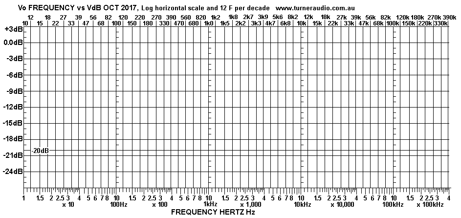
But for those who wish to plot the F response, here is a blank sheet you may download and print.

Fig 4. Blank graph sheet for plotting F response.
F-rspns-1Hz-400kHz-BLANK-2017.GIF
The graph should accommodate F response of anything you build for audio.

CATHODE FEEDBACK WINDINGS.
CFB windings will complicate the capacitance calculation because some of C between anodes appears at
cathodes Ck-k, The exact interaction with the split portions of Ca-a and also LL is difficult to predict.
But for a well interleaved OPT with say 5S+4P, there is little sign of any HF oscillation. I found the best
in a wound bobbin for say 2 x CFB layers and say 14 Anode layers was with CFB layer between an anode
layer and a Sec sec layer. The typical amount of CFB I like to use is between 12.5% and 20% of the total of all
Pri turns.
Consider 20% CFB with a KT88 with a fixed Eg2. This makes KT88 act like a triode with µ = 4.3, and Ra = 710r.
But instead of the electrostatic shunt NFB within the triode, the external loop FB is via linear transformer windings
and is series voltage FB so the THD is less with CFB than a real triode, the nearest type would be 300B.
But the KT88 acts las though it has 20% UL tap, which would give Ra 5k2 and UL µ = 31.2, but with ß = 0.2
and the UL µ is reduced to CFB µ = 4.3; the µ reduction by NFB = 1 / 7.25, or 16dB NFB.
But with a class A load RLa-k = 4k0, the amount of NFB = 12dB approx, so THD reduction factor = about
0.25. The PP connection with 2 x KT88 PP and CFB for 10W class A will give THD < 0.5%, and with 10dB
GNFB, THD < 0.16%.  it s  GF,with 8k0 R, so if there is 5% THD o,15Fof local series voltage NFB.
Thus the majority of error correction is done in the output stage but there is a tendency for HF oscillations
above 100kHz where there 2 cascaded applications of NFB, and open loop gain > 1.0, and phase shift >
180 degrees.
I found that placing Zobel networks using 2n2 + 2k2 across each anode portion of 1/2 primary helped to
prevent HF oscillations. The use of CFB windings does make the shelving networks used between input V1
and driver V2 stages more effective and easier to configure. There is little point to trying to further explain
the increased complexity with CFB, but it works well. Regardless of CFB windings, the Ca-a should be
minimised as much as possible.

The effect of Ca-a reducing bandwidth is reduced by the CFB so F response of an OPT with CFB and
no R load may well over 100kHz. 

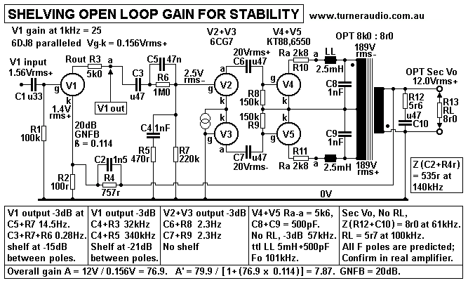
Fig 5. Shelving networks for typical amp, OPT 8k0 : 8r0.
basic-GNFB-shelving-gain-for-stability.GIF
I have had many emails from those who find their amplifier oscillates badly even with only 6dB GNFB.
This much NFB may make the sound worse, and 20dB should be possible for amp with 40% UL taps
for 2 x KT88. The values of following R + C must be optimised :-
C1+R1 for HPF pole 5Hz.
C2+R4, for advance of phase of Vac fed back.
C4+R5, for reducing HF gain V1 by -21dB between 32kHz and 340kHz.
C5+R6, for reducing LF gain V1 by -15dB between 25Hz and 2.5Hz.
R12+C10, for providing 5r7 load at above 100kHz to load the KT88 where speaker has
Z value much above its nominal value above 20kHz.

There is much more about gain shelving and F response with and without GNFB at basic-tube-3.html

Values of primary inductance, LL leakage inductance and C8+C9 shunt C are approximate, and cannot
be changed in any existing OPT. The real model on an OPT such as OPT-1A has many C and is is difficult
and confusing to try to any more modelling that the simple diagram shows above. 
The shelving of LF and HF gain with shelving networks will allow GNFB to be applied with poor quality OPT
with a low primary Lp and 10 times the LL shown above.  The F response at 1/2 full Po should have -3dB poles
at 5Hz and 65kHz where output load is correct, in this case 8r0. The R+C networks achieve
low overshoot and reduce ringing on 10kHz square waves when a 0.22 uF is connected
across ouput without any R load. At 1/10 full Po, uses of any C load between 2uF and 0.1uF
should be tolerated with response peak less than +6dB, and less than +3dB above 20kHz
where nominal 8r0 load is also connected.
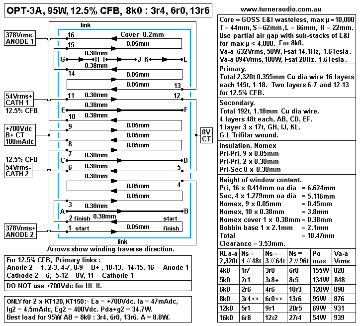
-------------------------------------------------------------------------------------------------- OPT-3A for high Po.

Fig 6. OPT-3A for 155W for 4k0 : 3r0 and 6r8.
OPT-3A-95W-PP-CFB-8k0-3r4-6r0-13r7-2017.GIF
OPT-3A is for KT120 only, to give up to 155W class AB1. At idle, KT120 has 50mAdc for Pda 35W. 
With Va-a = 848Vrms for RLa-a 5k0, Fsat = 20Hz, OK because the amp for high Po will never be
subjected to high bass levels.
Ea at +700Vdc is allowed because RLa-a is fairly high and lowest RLa = 1k0, Ia pk is less than 580mApk,
and which KT120 can do, providing Eg2 is high enough at about +440Vdc.
OPT-3A is very similar to OPT-1A, can be arranged with lower Ea = +500V and a quad of KT88, 6550
for Po = 100W, but much more initial class A Po.
--------------------------------------------------------------------------------------------------------------------------------------


SOME GENERAL NOTES ABOUT OPTs. For those who struggle to see what is inside a
transformer with layered windings :-
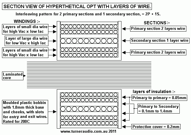
Fig 7.
OPT-basic-winding-layer-sections.gif
Fig 16 shows a cross section through a hypothetical transformer with concentric layered windings
neatly wound with an interleaving pattern of 2P + S, aka P-S-P ie, with two primary sections and
one secondary section located between each primary section. Fig 16 shows 4 layers of primary each
with 14t and 1 layer of secondary with 10t.

TR = 56 / 10 = 5.6. The ZR = TR squared = 31.36.

There is only one section of secondary, but if the bobbin space permitted, here could have been two
more secondary layers, one above and below existing primary sections, and interleaving pattern
could be S-P-S-P-S. The HF response will be far better with the additional P-S interfaces.
The number of LAYERS must NOT be confused with the number of SECTIONS. A winding "section" is
one or more layers of wires devoted solely to either primary or secondary current. There is no direct
connection between the sections for primary and sections for secondary. Because P and S are not
connected, this is an "isolation transformer".

But the primary could be connected in series with secondary which would give just one winding of 66t.
This makes the transformer into an "auto-transformer." Where this is done, the TR becomes 66t / 10t
= 6.6 and ZR = 43.56.
There is no primary or secondary, and there is only unshared part of winding, 56t, and and shared part
of winding, 10t. The current in shared 10t = current in load for 10t - current in unshared. This makes the
auto-transformer more efficient with less copper losses than same turns used on isolation transformer.

However, isolation transformers are much more common than auto-trans because the isolation is needed
where windings have different Vdc or where the transformer is for a PSU powered by mains, which
MUST NOT have direct connection to any secondary or 0V rail etc.

All isolation trans have P and S connected by shared magnetic field only. Auto transformers rely on
the same magnetic field but allow Vac of two windings to be in series connection. The auto transformer
needs to have its shared portion of winding well interleaved with the unshared part or else the HF response
is just as poor an isolation transformer with little interleaving. 

All tube amp OPTs have a primary load between say 100r and 10,000r, and secondary load of say 8r0,
so ZR varies between 12.5 : 1 to 1,250 : 1 to give TR between 3.53 : 1 and 35.3 : 1. To get good F
response there will always be at least 2 sec sections of one layer of thick wire with at least one section
of primary with many more turns of thin wire. The S-P-S arrangement may work OK for a small 6W OPT
for a single 6BQ5. But for a 300W amp with many tubes there may be 5 Pri sections each with 2
layers, and 6 Sec sections with one layer of thicker wire.

Each layer of secondary wire may be subdivided into "secondary sub sections" to allow varied series
and parallel connections to give variable load matches to suit a wide range of speaker ohm load values,
while keeping the anode load fairly constant and optimal.

There are no designs here which require rectangular section wire. Bifilar or trifilar windings have the
advantage of not having wires coming from a winding end between bobbin cheeks.
--------------------------------------------------------------------------------------------------------------------------
WINDING AND VARNISHING. Layers of wire and insulation will never be tight enough to prevent
small movements of wire due to audio signal generating magnetic forces which move wires to
cause sound to be produced by OPT. I suggest it is important to apply slow setting epoxy varnish
by brush to all windings and all surfaces of insulation as the bobbin is wound. All things needed to
wind an OPT should be immediately available, such as cut to size insulation.
This keeps the time spent winding to a minimum which should be less than 8 hours. Mobile phones
MUST be switched off, family life abandoned. The epoxy varnish applied at 9AM will still be soft at
5PM, bulging windings can be clamped tight with G-clamp and neatly sized wood blocks, and the
windings are flattened, and and allowed to cure for 2 days. Liquid varnish in bulge will squeeze
around to fill voids and excess will drip over bench to make a mess.
Clean up the mess up before it goes rock hard.

The end result Calls the Angels to their happy task of delivering great music to ears of us poor mortals.

The practice of hand winding OPT and varnishing as you wind can be extremely messy and epoxy
fumes given off by varnish can be quite toxic so a chemical mask must be worn.
There should be fume extractor fan. Wattyl 7008 two pack epoxy polyurethane floor varnish is OK,
and has long enough pot life to allow a full day for winding OPT-1A. This varnish kept getting onto my
hands and I needed a bowl of methylated spirits and roll of kitchen tissue paper to keep hands clean
as I wound. To gain winding skills, there is no substitute for practice, and I suggest beginners learn
by winding a perfectly layered and insulated choke before they even think about an OPT.
----------------------------------------------------------------------------------------
STRAPPING PATTERN LABELS. Strapping patterns 4A and 4C have board terminals labelled with
capital letters. Thus any terminal board can have 26 labels which is usually enough, without using
double letters, AA BB etc. For my OPTs in 300W amps, there were 12 sec windings needing 24 labels.
A strapping pattern for "16r0" is not shown because it is unlikely to ever be used. I have always used
numbers for primary connections with high volts, and letters for secondary connections with low volts.
This avoids confusion when winding or when servicing the amp.
See 300w-monobloc-about.html and output-trans-winding.html

STRAPPING TERMINALS. Where OPTs are made "open frame" and not potted, they should have terminal
boards on each side of bobbin with one side for primary connections with dangerous high volts and the
other side with a board shown above.
Open frame transformers MUST be covered with a box screwed to the chassis.
The best OPTs are potted in their own steel sheet box which helps screen them from stray magnetic fields
from power transformers.

TRANSFORMER POTTING. Try Googling "potted audio transformers".
A potted transformer must be bolted to steel sheet pot cover and have a 3mm thick terminal board well
attached to transformer and with turrets or 2mm brass bolts and nuts acting as turrets for connection of sleeved
wires from transformer or amp wiring.
The potted transformer should have 4 protruding bolts to fix to a chassis or have nuts welded to transformer
frame or brackets to allow bolts to screw into nuts when on the chassis. The chassis must have a pre-cut hole
to allow the terminals to project into sub chassis area to allow easy wiring. High Vac terminals should be well
positioned at 10mm centres to avoid large Vdc of Vac difference between any terminals. The low Vac Secondary
winding terminals must be carefully laid out and all labelled permanently and clearly.

All parts of the cores should be 10mm away from sides and top of pot, and board made smaller than pot plan
area to allow potting mix to be poured in until it fills the pot to underside of board. Before potting, the transformer
must have been well varnished and very dry. Once the potting is done, there is no way future access can be
gained to transformer.

A suitable potting compound is made by an Australian company Chemtools, and is sold from industrial
suppliers in many locations. For those in Canberra they might try M&G Industrial Supplies, 02 6280 7517.
The product you need is PTC-7000, Silicon Potting Compound in packs of 200grams, 1Kg, 5Kg.
This material will probably adhere well to clean bare steel pots. Mains and rectifier or audio frequency magnetic
fields can vibrate steel pots or boxes covering transformers, hence the need for the potting mix to adhere to pot.

Chokes should also be potted. Access to windings is only possible with amp upside down on a carpet lined bench.
The strapping alterations always makes non technical owners extremely worried, and if there is a way to fuck up
the strapping, and causing a short circuit, amp owners will definitely find it.

So you should understand that a great deal of thoughtful hand-crafting and tradework is involved with making
good OPTs and PTs and chokes.
------------------------------------------------------------------------------------------------
Forward to
PP OPT Calcs Page 4

Back to
OPT Calcs Page 3

Back to PP OPT Calcs Page 2

Back to PP OPT Calc Page 1

Index Page